HOW TO SEAL THE VALVE
The seal prevents leaks and is designed to prevent and contain them.
To ensure that the valve can shut off the flow of fluid well and prevent leaks, it is necessary to ensure that the valve is tightly sealed.
There are many reasons for valve leaks including: poor structural design, faulty sealing contact surfaces, loose fastening parts, poor fit between the valve body and the valve cover, and many more.
Valve sealing technology researches systematically and in depth, which mainly reflects in two aspects: the static seal and the dynamic seal: the first usually refers to the seal between two static surfaces, while the dynamic is mainly used to seal the valve stem , i.e. the fluid in the valve cannot escape with the movement of the valve stem.
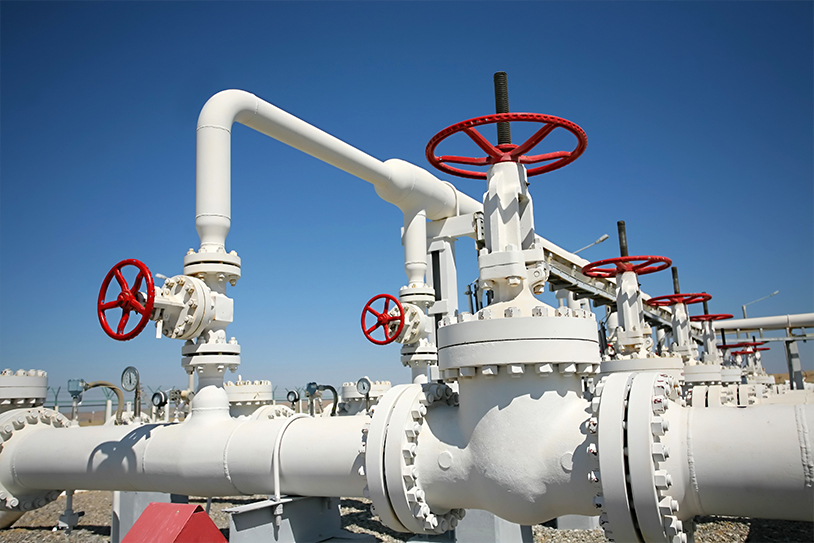
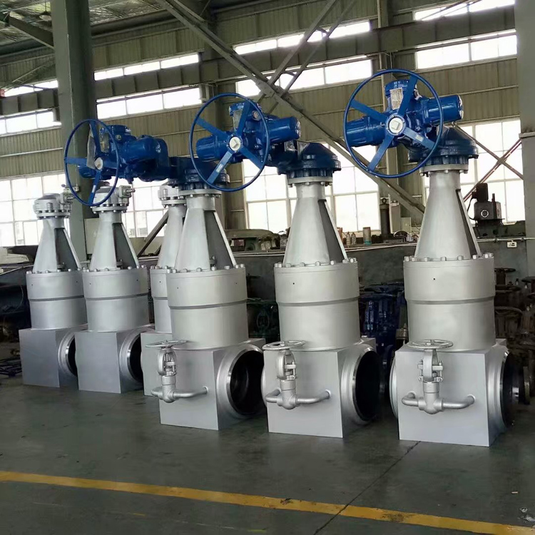
Rising stem gate valves typically have longer open-close strokes which can make sealing difficult if operated more frequently. In most cases, these valves are not operated more than once a week, sometimes even just once a year.
The clearance between the packing gland, valve stem and packing gland is very important: if the gap is large, linear motion can cause part of the sealing element to be crushed or foreign particles to be drawn through the sealing element. It is therefore possible to mount a cleaning ring at the bottom and in some cases at the top.
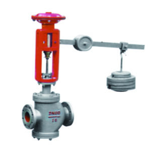
Globe valve usually adopts the lifting rod and rotary motion mode, and its sealing is the most difficult, because the valve stem will move in two directions at the same time and the packing assembly will gradually come into contact with the surface of the entire valve stem. Any misalignment or non-roundness of the valve stem can cause the packing element to break and leak. Similar to the case of gate valves, linear motion draws contaminant particles through the sealing element and into the process fluid.
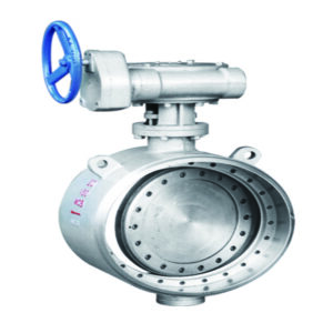
Ball, butterfly and plug valves are common quarter turn valves. When the valve stem is rotated ninety degrees relative to the sealing element, the valve can complete the entire process from opening to closing.
This movement pattern means the simplest seal because it has a much smaller stroke than other types of valves. Unlike linear motion models, quarter-turn motion does not easily drag foreign particles through the sealing element. It is worth paying attention to the eccentricity of the valve stem. Some sealing elements are extremely sensitive to actuator misalignment, which can also lead to reduced valve stem sealing performance.
There are many different models of quarter-turn valve glands, often resulting in a limited selection of sealing elements. In many cases the stuffing box is very shallow and it is difficult to achieve a tight seal under high pressure conditions.
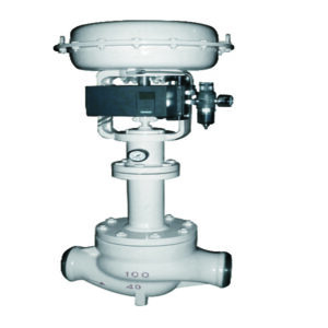
Control valve stem sealing is usually the most difficult, mainly due to frequent operation and the stem sealing effort cannot be too high. If a control valve experiences 100,000 stem cycles, other types of valves in the system tend to only experience 1,500. High cycle operation can cause wear of the sealing elements, which can degrade sealing performance over time. To optimize fluid control performance, the control valve stem cannot withstand excessive friction, so the sealing effort acting on the control valve is significantly less than that of the manual valve. If the sealing element causes the valve stem to experience excessive friction, the valve action will retard or suffer from speed deviation, resulting in excessive valve stem action and reduced fluid control performance. Linear control valves are more difficult to seal than rotary control valves. Similar to the quarter turn valve, the valve stem of the rotary control valve has only a circular motion mode and the surface of the valve stem that needs to be sealed is significantly smaller than that of the linear control valve.
The stem material of specialty metallurgical valves is relatively soft, so care should be taken when selecting sealing components. Ideally, the sealing element material is softer than the stem material to minimize stem wear. The yield strength of the gland bolts of some special metallurgical valves is relatively low and it is necessary to avoid that the load of the sealing element is close to the maximum tolerable stress.
For small valves, the annular section between the valve stem and the inner wall of the packing gland is small, but this is not necessarily a good thing as it limits the selection of sealing elements in some cases. Small valves typically have an annular cross section of only 0.125 “, making it difficult to install robust, innovative design sealing elements. The large valve can also cause problems! Oversizing can cause excessive loads on the stem and packing set. When the valve vibrates, the forces generated may be too large for standard sealing elements. The temperature difference between the different sections of large valves is also high, which can lead to structural deformations.
For most types of valves, the ideal ratio of the packing size to a cavity height is 3-5 times the cross-sectional diameter. If it is a quarter turn valve with low sealing requirements, it can seal effectively even if the stuffing box is shallow. A gland that is too deep at the beginning means that the seal assembly tends to consolidate, resulting in loss of seal stress and consequent leakage. The second is the high friction on the valve stem, which can become a hindrance in some applications. Depending on the specific conditions of the various sealing systems, the sealing element and the valve body surface treatment process must be reasonably matched. Taking O-rings as an example, the surface of the valve body must be relatively smooth, while other sealing elements may require rougher surfaces for a better seal. In many cases, the stem surface of new valves is too smooth, resulting in excessive friction and a stick-slip effect with the sealing element. Low-friction sealing elements such as polytetrafluoroethylene (PTFE) seals can avoid these unwanted phenomena.
Key factors in valve packaging and sealing
COMPRESSED PACKAGING The packaging is a special mechanical seal between two different environments and is also used for a type of seal used for example in globe valves.
The packing gland of a
regulating valve deserves particular attention because its incorrect use can compromise the performance of the whole valve.
The maintenance rules therefore become very important because replacement or adjustment operations not properly carried out or improvised can make the control valve inefficient.
The principle of operation of the stuffing box is shown in Figure 1.

Figure 1
The pressing force resulting from the pressing of the gland produces a radial pressure which results in a sealing effect. Radial pressure is distributed exponentially along the entire length of the packing. To keep the packing “dry”, the radial pressure on the inner ring must be at least equal to the internal pressure of the system, which means that the radial pressure on the outer ring is much higher, which is too high in most applications (resulting in Excessive friction, shaft wear and pneumatic seal failure). Therefore, in most
applications, the compression force should be adjusted to allow a slight leakage of the packing on the last ring, that is, the radial pressure on this ring is slightly lower than the internal pressure of the system. However, this will result in some leakage on most packing rings if the gland is adjusted to the minimum compression that does not produce leakage.
Another factor that complicates the issue of optimal gland compaction is that some packings can expand under use, for example, when the temperature Adding a little preload may be necessary. In addition, to compensate for packing wear and slack and to maintain a satisfactory seal, it is necessary to periodically re-tighten the gland.
When ordinary
packing materials are used, the ratio of the radial pressure generated to the axial pressure applied when pressing the gland is about 0.6~0.7, and the typical radial pressure along the entire stuffing box is shown in Figure 2.
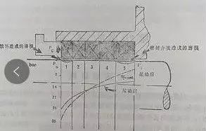
Figure 2
Packing remains the primary choice for many applications, especially where large stuffing boxes and heavy loads are used, such as process pumps, steam supply, and gravity water treatment. Packing seals also have the advantage that they can be used in rotating applications in addition to reciprocating applications. For many reciprocating jobs, especially in large, heavy-duty applications, a flexible seal assembly or a single seal can replace the packing, unless minimal leakage is required, and a mechanical shaft seal may be more appropriate. It is worth noting, however, that with the widespread use of mechanical seals, there is no sign of a reduction in the need for basket packing seals.
Fillers are basically soft (deformable) cross-sections, although their softness varies widely. A few levels of the packing always contain lubricant, and during use, with excessive pressure or overheating, the lubricant will be lost, the volume of the packing will be smaller, and the radial pressure will drop, causing leakage from the surface.
Where lubrication is problematic, or where some cooling of the stuffing box is required, additional lubricant/coolant can be fed into the center of the stuffing box, as shown in Figure 3.
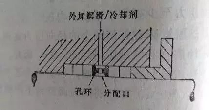
Figure 3
The degree of refrigeration by this method is limited, and at higher temperatures, the entire stuffing box body may have to be operationally cooled in order to keep the operating temperature of the stuffing box within the service temperature limits of the packing.Since fibers require high pressure shrinkage to cause greater friction and overheating due to lack of proper lubrication, plus accumulated slip/etc., a number of problems arise from this, which can be addressed by using a recently developed PTFE coating Dispersed aramid cellulose-based filler to solve.
Filler size
Compression packings generally have a roughly square cross-section (although patterned woven packings can be used on reciprocating piston rods). and valve stem; bulk packing can be used to seal valves and stuffing boxes of some pumps). Therefore, most fillers are made in standard cross-section sizes above 6mm (1/46in) “square”. Section size is largely arbitrary
But as a general guideline, when the shaft diameter is 12mm (1/2in), the groove width is about 25% of the shaft (or rod) diameter, and when the shaft diameter is about 150mm (6in), the groove width is reduced to the shaft diameter 10% of the diameter size.
There is no certain rule as to how many packing circles are the best, but for general work, it is typical to use 4 circles or 5 circles of square circles, as shown in Figure 4 and Figure 5.
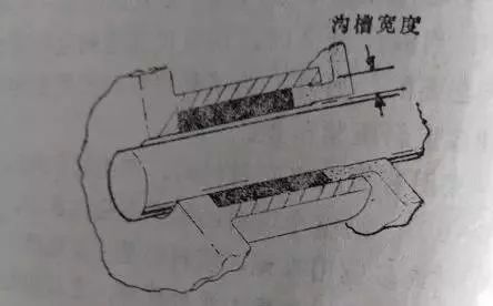
Figure 4

Figure 5
Stuffing box structure
As shown in Figure 5a, the stuffing box structure for handling clean, abrasive-free fluids under pressure is simple. The specific requirement is to ensure that there is a proper guide cone at the mouth of the stuffing box, so as not to damage the packing during assembly, and it is also required that the surface of the stuffing box has a fairly good surface finish. It is generally believed that 2.5um (64uin) Ra meets most of the requirements for use.
In the applications where the sealed medium contains abrasive particles, it is hoped that the abrasive particles will not enter the packing sealing area as much as possible. This can be accomplished by introducing an appropriate flush through an orifice ring in the center of the stuffing box, as shown in Figure 5b. It should be pointed out that the leakage controlled in this case is the leakage of the flushing fluid, which will also leak back into the medium due to the distribution of the meridional pressure. Where flushing with an appropriate fluid is not possible, a grease flush is an option, as shown in Figure 5c. In this case, the grease must be clean and compatible with the medium.
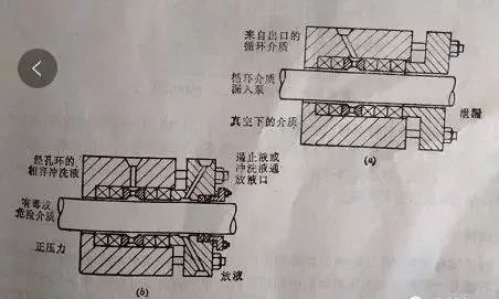
Figure 6
Figure 6 shows two other stuffing box configurations. In Figure 6a, the pressure of the medium being treated is below atmospheric pressure, so a liquid barrier is required to prevent air from entering the medium through the stuffing box. This liquid barrier is drawn from the media outlet through the orifice ring and fed into the stuffing box. The leakage controlled in this case is the leakage of the medium.
The treated medium in Figure 6b is toxic or hazardous, so a flush-type stuffing box is also used to supply the primary barrier. This is supported by a containment passage (flushing loop) in the packing gland, and an auxiliary packing block to prevent leakage.
Traditional material
Traditional forms of filler based on lubricated fiber ropes are still common and have been widely used. The range of materials used for this filler is quite broad (see Table 1A, only some of which are listed), and this range is further expanded by the introduction of synthetic cords to improve some properties, however, it has been proved that artificial The advantages of silk and nylon are limited. Plant fibers are generally suitable for oil-water and non-corrosive chemical media with a working temperature of not more than
90 °C and a moderate friction speed (not higher than 8m/s). Cotton and linen are the most widely used fibers, followed by hemp. Ramie, jute and sisal have largely disappeared.Asbestos rope is the traditional material of choice for high temperature service conditions (up to 320″C) and high friction speed. Of course, the problem of asbestos harmful to human health is indeed a matter of concern, and crocidolite In fact, it has been stopped. However, crocidolite has good corrosion resistance. Few people have raised objections to white asbestos (hydrated magnesium silicate asbestos). White asbestos has become the most important rope used for asbestos fillers. Especially as a fibrous material, which is firmly bonded by impregnation during the manufacture of fillers, it does not emit asbestos dust, which is the main source of health hazards cited.
Traditional lubricant
Fiber rope fillers are always lubricated, except for special applications where dry fillers are actually required. Graphite is a lubricant that is often added to the cross section of the filler, and it can provide good self-lubrication in many applications that work under dry conditions or in contact with non-lubricating fluids.
Therefore, graphite lubricants are particularly suitable for the supply of steam, water, especially salt water equipment. However, in some cases, the presence of loose graphite may be detrimental; or when the packing is run against the stainless steel rod, the graphite may cause localized corrosion of the steel due to electrolysis. Another available lubricating impregnant that can solve this problem is mica. These lubricants, along with molybdenum disulfide and teflon, are still the standard “dry” lubricants to this day.
Traditional “blended” lubricants like tallow have been replaced by mineral oil, butter, paraffin and soap. Silicone greases are designed for high temperature applications with asbestos fillers, but are currently considered unsuitable for applications in contact with food and drinking water. Lubricants used in these types of applications The percentages of lubricants typically used vary from application to application. Therefore, fillers prepared for high-speed motion, especially high-speed rotary motion, should generally be softer, so as to remain flexible for a long time and be able to contain a larger percentage of lubricant. Fillers that work only under static service conditions generally do not need to add lubricants at all. Fillers used in reciprocating applications can be reinforced with wear-resistant wire rather than lubricants, perhaps with a graphite sheath. Other varieties of fillers may be reinforced with a wear-resistant soft wire while also being dipped in a lubricant. The amount of wear-resistant soft wire should both ensure continuous lubrication of the shaft and help conduct heat from the working surface.
Rope packing vs braided packing
Braid fillers are made up of multiple strands of wire braided in conventional or modified braid fashion, with each strand forming a gap to hold the lubricant. The rope layers can be matched according to specific
working conditions, for example, when used for rotary seals, they are braided according to the rotation of the shaft, so that the wear of individual fibers will not seriously affect the overall performance of the packing section.
Braided packing can be constructed in two different ways. The continuous braided packing consists of single strands of yarn woven together in a tubular shape, in a similar manner, layer by layer to make the desired cross-section. The other is the twill weaving method (as a deformation and mesh weaving method), both methods can be made into denser fillers, which have a higher surface density; but keep the space of the lubricant small, so In the case that the filler does not peel off, it has better performance than braided rope fibers (like a braided filler)

Figure 7
The weaving section can be woven into a square to form a circle. In the latter case, the square section is usually made by simply passing through a pulley die after weaving and dipping in lubricant. In practice, manufacturers have developed their own special forms of braided or braided packing structures, such as cross-type braided packing (Crossley) or super braided packing (Latty International), designed to overcome the common or “typical” The disadvantages of braided packing. Figure 7 shows an example of two carefully
developed cross-sections that are durable, uniform, and impermeable, while also exhibiting good flexibility.
Modern Graphitized Fossil Wool Filler
The appearance of graphitized fossil wool fillers has been attributed to some recent work in the production of a direct blend of graphite and asbestos, rather than in the manufacture of surface coatings. Low friction, good high temperature performance.
Polytetrachloroethylene packing
PTFE, with its excellent resistance to chemical attack, and its outstanding properties as a low-friction material make it an attractive choice for fillers. The downsides of this material property are low strength, poor thermal conductivity, and a tendency to shrink with increasing temperature (ie, have a negative coefficient of thermal expansion). When this material is used in combination with a rope filler (usually asbestos rope) as a lubricant, its thermal shrinkage properties limit the maximum friction velocity of the material to about 8~10m/s and the maximum service temperature to about 250~290C
However, thermal conductivity can be improved by adding graphite. PTFE/graphite fillers made by extrusion are among the most attractive and useful modern filler types, with better properties than ordinary rope fillers, especially This is especially true in terms of longevity and reduced shaft or rod damage.
Orientation and location of the valve
Horizontally mounted valves are prone to excessive side loads compared to vertically mounted valves. Some valves are installed on pipelines or platforms that are constantly vibrating. If auxiliary support is provided to the valve stem, it is beneficial to maintain its sealing performance. Some valves are close to high temperature equipment, and heat radiation has a negative effect on sealing performance.
Process fluid within the valve
Chemical compatibility is important; particulates in abrasive fluids can degrade seal element performance. Usually the sealing element at the bottom will be less effective than the upper layer, because only part of the load applied by the gland can be transmitted to the bottom. In this case, particles in the medium can enter the sealing element and degrade its performance. Fluids containing suspended particles will evaporate and crystallize on the side of the packing close to the outside air, causing problems with the actuator. When the fluid is hermetically isolated by the sealing element, a pressure drop occurs on both sides and the fluid may undergo a phase change. The expansion during the phase transition is very severe, and the sealing element must be strong enough to withstand the forces created by the phase transition. Take low-hardness O-rings as an example, they are more likely to be damaged in such fluids, especially small-molecule fluids.
Fluid temperature
Below 550°F, high molecular weight polymers such as polytetrafluoroethylene (PTFE) and Aramide fibers can be used. O-rings are often used in non-critical service below 400°F. Carbon graphite packing is commonly used for high temperature fluids above 550°F. At lower temperatures, carbon graphite packing requires greater sealing stress, resulting in greater stem friction. Compared with other materials, it can withstand lower cyclic loads. At extremely high temperatures, above 850 ° F, the carbon graphite packaging and active ingredients used to improve the sealing properties of the material will deteriorate in an oxidizing atmosphere. The countermeasure is to extend the bonnet to open the gap between the packing gland and the valve body to reduce the influence of the high temperature fluid on the packing. Parts with low thermal conductivity can also reduce the sealing element temperature, such as installing a ceramic gasket between the gland and the sealing element.
Pressure
The higher the pressure, the harder it will be to seal. From the Bernoulli equation, the flow variable is proportional to the square of the pressure variable. It is easy to understand that the sealing difficulty of a 1500 lb valve is much higher than that of a 150 lb valve. In high-pressure applications, it is especially necessary to ensure that the load requirements, sealing element design and sealing performance can be compatible.
Sealing performance
The most important of all concerns is undoubtedly the sealing performance requirement. Many industries, particularly the water treatment industry, can tolerate some level of visible leakage. Leaking material carries solid particles which, once accumulated, can plug the leak. Such conditions are acceptable, so small losses are not very harmful. In some other industries, visible losses are a big deal. However, for invisible leaks, detection is generally limited to routine factory methods. The fugitive leakage requirements for sealing elements are much higher and are frequently tested and / or monitored frequently. Loss is generally not visible, the unit of measurement is parts per million (PPM), and standards are becoming increasingly stringent. Some fluids are extremely dangerous, such as carcinogens, and some are lethal even in trace amounts. This requires additional precautions, a backup system, a double seal system and a leak hole between the two systems for monitoring. Bellows seal valves have a back-up sealing system and can be used
for such hazardous fluids.
These indications and information are used to
help you clarify the variables involved in a valve,
so that you can select the sealing technology that best suits your needs.
The more complete the information you have,
the easier it will be to choose the most suitable sealing solution.
