Valve sealing surface material

Valve sealing surface material

Valve sealing surface material is what we need to pay attention to when buying valves. We provide a variety of sealing surface material options to meet the requirements of different industries. We are a professional valve solution supplier from China, producing and customizing valves for hundreds of customers and dozens of industries around the world!

why choose xinhui valve !

Our wish is to get you here without having to look for anyone else!

Valve sealing surface material
3

Valve sealing surface material​

We have hundreds of industrial valves for you to choose from!

6

Novel valve type

Every year research and development of novel valves are put into production!

3

Customized valve types​

Fully customized valve according to customer needs!

You Need to Know About Valve sealing surface material

Valve sealing surface material

The valve sealing surface material can be of many types.

SOFT SEALING MATERIAL

Butadiene rubber (NBR)

Butadiene rubber has excellent oil resistance and heat resistance is better than natural rubber and styrene-butadiene rubber. Its air tightness and water resistance are optimal and it is suitable for petroleum products, benzene, toluene, water, acid and alkaline medium with temperature of -60 ~ + 120 degrees.

 Fluorinated rubber (FKM)

Fluororubber is resistant to heat, acid and alkali, oil, saturated water and steam, with a small compression set and good air tightness. It is used for for petroleum products, water, acid and alcohol at temperatures between -30 and +220 degrees.

 Polytetrafluoroethylene (PTFE)

It possesses other resistance to extreme heat, chemical corrosion, low coefficient of friction, but low mechanical strength, easy sliding and low elasticity. It is suitable for corrosive fluids with a temperature lower than or equal to 170 degrees.

HARD SEALING MATERIAL

 Copper alloy

It has good corrosion resistance and wear resistance in water or steam and is suitable for fluids with PN≤1.6MPa and temperature not higher than 200 degrees. It can be fixed on the body by ring structure or surface and casting methods. The commonly used grades are ZCuAl10Fe3 (aluminum bronze), ZCuZn38Mn2Pb2 (cast brass).

 Chromed stainless steel

It offers good corrosion resistance and is usually used for water, steam and oil, and the temperature does not exceed 450 degrees. The commonly used grades are 2Cr13 and 1Cr13.

 Alloy of stellite

It is resistant to corrosion, erosion and scratches. It is suitable for valves of various purposes and various fluids with a temperature of -268 to +650 degrees, especially strong corrosive fluids. Due to the high price it is often used for the construction of surfaces.

 Nickel-based alloys

There are three commonly used sealing surface materials: Monel, Hastelloy B and Hastelloy C. Monel is the primary material that resists corrosion from hydrofluoric acid and is suitable for alkali, salt, food and airless acidic solvents at temperatures of – 240 to +482 degrees. Hastelloy B and Hastelloy C are the most resistant to corrosion and for this they are suitable for corrosive mineral acid, sulfuric acid, phosphoric acid, wet HCI gas and strong oxidizing medium at a temperature of 371 degrees (hardness 14RC). At the same time they are also used for solutions free of hydrochloric acid and strong oxidizing media with a temperature of 538 degrees (23RC). 

 Iron-based alloys

Iron-based alloy is a newly developed and highly innovative sealing surface material. Its wear and scratch resistance are better than 2Cr13 and it also has good corrosion resistance, so much so that it can replace 2Cr13. It is suitable for non-corrosive fluids with temperature lower than or equal to 450 degrees.


More Valve related articles

I believe you will not regret your choice​

Why choose XinHui valve?​

Customized on demand​

We very much welcome customers to bring your requirements in the industry, our industrial valve solutions include customized on demand! Use the best materials to produce standard compliant valves, If you need valve customization services, please contact us immediately

Valve quality​

Xinhui valve strictly controls the quality of the products in each process; on the other hand, it improves the work quality of the employees; and constantly pursues the high performance and high quality of the products, and is committed to becoming the preferred brand of valve products for the majority of users. . ​

Professional Services

Our salesman will answer your professional industry questions, product questions, transportation questions, etc. Our service personnel are online 7*12 hours. If you encounter time difference problems, please wait patiently for our reply, and we will reply you as soon as possible The problem.​

High and new technology​

As a high-tech enterprise in China, we can provide complete valve sample drawings, technical support for valve production process, technical support such as maintenance manuals, and strength calculation books. Frequently Asked Questions about Valve Operation.

R&D innovation​

Xinhui Valve has invested a lot of manpower and funds in the innovative research and development of valves, and opened laboratories, inspection rooms, and R&D rooms. 20 kinds of new products are developed every year. Customized industry-specific valves for customers, dozens of products under severe valve conditions.


International Standard

The valves we produce meet various international testing indicators, and all kinds of valves are manufactured and accepted according to relevant domestic standards such as GB and JB, as well as international standards such as ANSI, API, JIS, and BS. DIN. Please contact us for special production standards.​

We are not only a manufacturer of valves, but also a disseminator of industry knowledge

REQUEST A QUOTE FOR MORE DETAILS

OEM & ODM XinHui valve Applications

D341H国标法兰式蝶阀Butterfly valve

xxxxxx炼金最佳

单击 “编辑” 按钮更改此文本。这是测试文本。


x

D341H国标法兰式蝶阀Butterfly valve

xxxxxx石油专用....

单击 “编辑” 按钮更改此文本。这是测试文本。


x

D341H国标法兰式蝶阀Butterfly valve

xxxxxx

单击 “编辑” 按钮更改此文本。这是测试文本。


x

D341H国标法兰式蝶阀Butterfly valve

xxxxxx

单击 “编辑” 按钮更改此文本。这是测试文本。


x

D341H国标法兰式蝶阀Butterfly valve

xxxxxx

单击 “编辑” 按钮更改此文本。这是测试文本。


x

Valve sealing surface material

THE 6 FACTORS TO CONSIDER WHEN CHOOSING THE VALVE SEAL SURFACE MATERIAL
The quality of the materials for the sealing surface directly affects the life of the valve, therefore when selecting the following factors must be considered:
1. Corrosion resistance
“Corrosion” is the process in which the sealing surface is damaged under the action of the medium.
For such damage to the surface, the sealing performance cannot be guaranteed, and the corrosion
resistance of the sealing material mainly depends on the full score and chemical stability of the
material.
2. Anti-scratch
Scratch is the damage to material caused by friction as the sealing surfaces move relative to each
other. Such damage will inevitably cause damage to the sealing surface, so the material of the
sealing surface must have good internal inspection performance and must be a gate valve. The
scratchability of a material is often determined by the internal properties of the material.
3. Corrosion resistance
“Erosion” is the process of destroying the sealing surface when the medium passes through the
sealing surface at high speed. Sealing damage has a great influence, so corrosion resistance is also
one of the important requirements of sealing surface materials.
4. Hardness
The hardness will be greatly reduced at the specified working temperature.
5. Linear expansion coefficient
The linear expansion coefficient of the sealing surface and the body material should be similar,
which is more important for the structure of the sealing ring to avoid additional stress and loosening at high temperature.
6. Additional special requirements
When used at high temperature, there must be sufficient anti-oxidation, thermal fatigue, thermal
cycle and other problems. Then depending on the valve and usage, only a few requirements can be
focused on. For example, valves used in high-speed media should pay special attention to the
corrosion resistance requirements of the sealing surface. When the medium contains solid
impurities, the sealing surface material with high hardness should be selected. 
 
HOW TO SEAL THE VALVE
The seal prevents leaks and is designed to prevent and contain them.
To ensure that the valve can shut off the flow of fluid well and prevent leaks, it is necessary to ensure that the valve is tightly sealed.
There are many reasons for valve leaks including: poor structural design, faulty sealing contact surfaces, loose fastening parts, poor fit between the valve body and the valve cover, and many more.
Valve sealing technology researches systematically and in depth, which mainly reflects in two aspects: the static seal and the dynamic seal: the first usually refers to the seal between two static surfaces, while the dynamic is mainly used to seal the valve stem , i.e. the fluid in the valve cannot escape with the movement of the valve stem. 
 

a3640385b92e416cb876c06c884a97af

Type of valve & impact on the choice of sealing solution
Rising stem gate valves typically have longer open-close strokes which can make sealing difficult if operated more frequently. In most cases, these valves are not operated more than once a week, sometimes even just once a year.
The clearance between the packing gland, valve stem and packing gland is very important: if the gap is large, linear motion can cause part of the sealing element to be crushed or foreign particles to be drawn through the sealing element. It is therefore possible to mount a cleaning ring at the bottom and in some cases at the top.
Globe valve usually adopts the lifting rod and rotary motion mode, and its sealing is the most difficult, because the valve stem will move in two directions at the same time and the packing assembly will gradually come into contact with the surface of the entire valve stem. Any misalignment or non-roundness of the valve stem can cause the packing element to break and leak. Similar to the case of gate valves, linear motion draws contaminant particles through the sealing element and into the process fluid.
Ball, butterfly and plug valves are common quarter turn valves. When the valve stem is rotated ninety degrees relative to the sealing element, the valve can complete the entire process from opening to closing.
This movement pattern means the simplest seal because it has a much smaller stroke than other types of valves. Unlike linear motion models, quarter-turn motion does not easily drag foreign particles through the sealing element. It is worth paying attention to the eccentricity of the valve stem. Some sealing elements are extremely sensitive to actuator misalignment, which can also lead to reduced valve stem sealing performance.
There are many different models of quarter-turn valve glands, often resulting in a limited selection of sealing elements. In many cases the stuffing box is very shallow and it is difficult to achieve a tight seal under high pressure conditions.
Control valve stem sealing is usually the most difficult, mainly due to frequent operation and the stem sealing effort cannot be too high. If a control valve experiences 100,000 stem cycles, other types of valves in the system tend to only experience 1,500. High cycle operation can cause wear of the sealing elements, which can degrade sealing performance over time. To optimize fluid control performance, the control valve stem cannot withstand excessive friction, so the sealing effort acting on the control valve is significantly less than that of the manual valve. If the sealing element causes the valve stem to experience excessive friction, the valve action will retard or suffer from speed deviation, resulting in excessive valve stem action and reduced fluid control performance. Linear control valves are more difficult to seal than rotary control valves. Similar to the quarter turn valve, the valve stem of the rotary control valve has only a circular motion mode and the surface of the valve stem that needs to be sealed is significantly smaller than that of the linear control valve.
The stem material of specialty metallurgical valves is relatively soft, so care should be taken when selecting sealing components. Ideally, the sealing element material is softer than the stem material to minimize stem wear. The yield strength of the gland bolts of some special metallurgical valves is relatively low and it is necessary to avoid that the load of the sealing element is close to the maximum tolerable stress. 
Size of the valve 
For small valves, the annular section between the valve stem and the inner wall of the packing gland is small, but this is not necessarily a good thing as it limits the selection of sealing elements in some cases. Small valves typically have an annular cross section of only 0.125 “, making it difficult to install robust, innovative design sealing elements. The large valve can also cause problems! Oversizing can cause excessive loads on the stem and packing set. When the valve vibrates, the forces generated may be too large for standard sealing elements. The temperature difference between the different sections of large valves is also high, which can lead to structural deformations.
For most types of valves, the ideal ratio of the packing size to a cavity height is 3-5 times the cross-sectional diameter. If it is a quarter turn valve with low sealing requirements, it can seal effectively even if the stuffing box is shallow. A gland that is too deep at the beginning means that the seal assembly tends to consolidate, resulting in loss of seal stress and consequent leakage. The second is the high friction on the valve stem, which can become a hindrance in some applications. Depending on the specific conditions of the various sealing systems, the sealing element and the valve body surface treatment process must be reasonably matched. Taking O-rings as an example, the surface of the valve body must be relatively smooth, while other sealing elements may require rougher surfaces for a better seal. In many cases, the stem surface of new valves is too smooth, resulting in excessive friction and a stick-slip effect with the sealing element. Low-friction sealing elements such as polytetrafluoroethylene (PTFE) seals can avoid these unwanted phenomena.
Key factors in valve packaging and sealing
COMPRESSED PACKAGING The packaging is a special mechanical seal between two different environments and is also used for a type of seal used for example in globe valves.
The packing gland of a regulating valve deserves particular attention because its incorrect use can compromise the performance of the whole valve.
The maintenance rules therefore become very important because replacement or adjustment operations not properly carried out or improvised can make the control valve inefficient.
The principle of operation of the stuffing box is shown in Figure 1. 

3df96b8929df4eb8860382c3081973d2

Figure 1
The pressing force resulting from the pressing of the gland produces a radial pressure which results in a sealing effect. Radial pressure is distributed exponentially along the entire length of the packing. To keep the packing “dry”, the radial pressure on the inner ring must be at least equal to the internal pressure of the system, which means that the radial pressure on the outer ring is much higher, which is too high in most applications (resulting in Excessive friction, shaft wear and pneumatic seal failure). Therefore, in most
applications, the compression force should be adjusted to allow a slight leakage of the packing on the last ring, that is, the radial pressure on this ring is slightly lower than the internal pressure of the system. However, this will result in some leakage on most packing rings if the gland is adjusted to the minimum compression that does not produce leakage.
Another factor that complicates the issue of optimal gland compaction is that some packings can expand under use, for example, when the temperature Adding a little preload may be necessary. In addition, to compensate for packing wear and slack and to maintain a satisfactory seal, it is necessary to periodically re-tighten the gland.
When ordinary packing materials are used, the ratio of the radial pressure generated to the axial pressure applied when pressing the gland is about 0.6~0.7, and the typical radial pressure along the entire stuffing box is shown in Figure 2. 
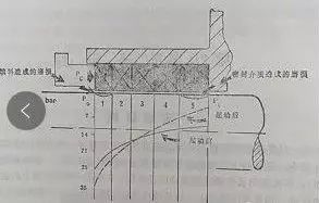
2f635b21d2ef4f5cb14e3a35c38eb066

Figure 2 
Packing remains the primary choice for many applications, especially where large stuffing boxes and heavy loads are used, such as process pumps, steam supply, and gravity water treatment. Packing seals also have the advantage that they can be used in rotating applications in addition to reciprocating applications. For many reciprocating jobs, especially in large, heavy-duty applications, a flexible seal assembly or a single seal can replace the packing, unless minimal leakage is required, and a mechanical shaft seal may be more appropriate. It is worth noting, however, that with the widespread use of mechanical seals, there is no sign of a reduction in the need for basket packing seals.
Fillers are basically soft (deformable) cross-sections, although their softness varies widely. A few levels of the packing always contain lubricant, and during use, with excessive pressure or overheating, the lubricant will be lost, the volume of the packing will be smaller, and the radial pressure will drop, causing leakage from the surface.
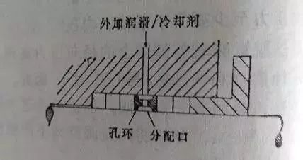
Where lubrication is problematic, or where some cooling of the stuffing box is required, additional lubricant/coolant can be fed into the center of the stuffing box, as shown in Figure 3. 
bbabdc35c28d4b71aad7b5ebac6f89d8

Figure 3
The degree of refrigeration by this method is limited, and at higher temperatures, the entire stuffing box body may have to be operationally cooled in order to keep the operating temperature of the stuffing box within the service temperature limits of the packing.Since fibers require high pressure shrinkage to cause greater friction and overheating due to lack of proper lubrication, plus accumulated slip/etc., a number of problems arise from this, which can be addressed by using a recently developed PTFE coating Dispersed aramid cellulose-based filler to solve.
Filler size
Compression packings generally have a roughly square cross-section (although patterned woven packings can be used on reciprocating piston rods). and valve stem; bulk packing can be used to seal valves and stuffing boxes of some pumps). Therefore, most fillers are made in standard cross-section sizes above 6mm (1/46in) “square”. Section size is largely arbitrary
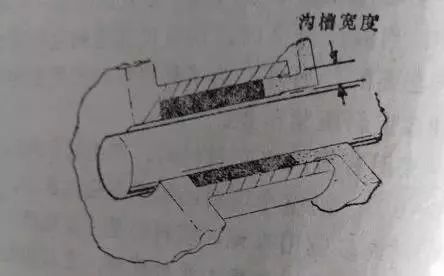
But as a general guideline, when the shaft diameter is 12mm (1/2in), the groove width is about 25% of the shaft (or rod) diameter, and when the shaft diameter is about 150mm (6in), the groove width is reduced to the shaft diameter 10% of the diameter size.
There is no certain rule as to how many packing circles are the best, but for general work, it is typical to use 4 circles or 5 circles of square circles, as shown in Figure 4 and Figure 5. 
3a7c423d0c3a450db97df6311b9e10f3

Figure 4 

180f1aa9233c4e9ab67f6e04fa83cd35

Figure 5 
Stuffing box structure
As shown in Figure 5a, the stuffing box structure for handling clean, abrasive-free fluids under pressure is simple. The specific requirement is to ensure that there is a proper guide cone at the mouth of the stuffing box, so as not to damage the packing during assembly, and it is also required that the surface of the stuffing box has a fairly good surface finish. It is generally believed that 2.5um (64uin) Ra meets most of the requirements for use.
In the applications where the sealed medium contains abrasive particles, it is hoped that the abrasive particles will not enter the packing sealing area as much as possible. This can be accomplished by introducing an appropriate flush through an orifice ring in the center of the stuffing box, as shown in Figure 5b. It should be pointed out that the leakage controlled in this case is the leakage of the flushing fluid, which will also leak back into the medium due to the distribution of the meridional pressure. Where flushing with an appropriate fluid is not possible, a grease flush is an option, as shown in Figure 5c. In this case, the grease must be clean and compatible with the medium.
9f1bd2649d1c4797aec5e56f0a3f630d

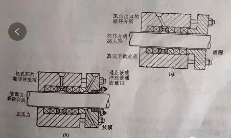
Figure 6 
Figure 6 shows two other stuffing box configurations. In Figure 6a, the pressure of the medium being treated is below atmospheric pressure, so a liquid barrier is required to prevent air from entering the medium through the stuffing box. This liquid barrier is drawn from the media outlet through the orifice ring and fed into the stuffing box. The leakage controlled in this case is the leakage of the medium.
The treated medium in Figure 6b is toxic or hazardous, so a flush-type stuffing box is also used to supply the primary barrier. This is supported by a containment passage (flushing loop) in the packing gland, and an auxiliary packing block to prevent leakage.
Traditional material
Traditional forms of filler based on lubricated fiber ropes are still common and have been widely used. The range of materials used for this filler is quite broad (see Table 1A, only some of which are listed), and this range is further expanded by the introduction of synthetic cords to improve some properties, however, it has been proved that artificial The advantages of silk and nylon are limited. Plant fibers are generally suitable for oil-water and non-corrosive chemical media with a working temperature of not more than
90 °C and a moderate friction speed (not higher than 8m/s). Cotton and linen are the most widely used fibers, followed by hemp. Ramie, jute and sisal have largely disappeared.Asbestos rope is the traditional material of choice for high temperature service conditions (up to 320″C) and high friction speed. Of course, the problem of asbestos harmful to human health is indeed a matter of concern, and crocidolite In fact, it has been stopped. However, crocidolite has good corrosion resistance. Few people have raised objections to white asbestos (hydrated magnesium silicate asbestos). White asbestos has become the most important rope used for asbestos fillers. Especially as a fibrous material, which is firmly bonded by impregnation during the manufacture of fillers, it does not emit asbestos dust, which is the main source of health hazards cited.
Traditional lubricant
Fiber rope fillers are always lubricated, except for special applications where dry fillers are actually required. Graphite is a lubricant that is often added to the cross section of the filler, and it can provide good self-lubrication in many applications that work under dry conditions or in contact with non-lubricating fluids.
Therefore, graphite lubricants are particularly suitable for the supply of steam, water, especially salt water equipment. However, in some cases, the presence of loose graphite may be detrimental; or when the packing is run against the stainless steel rod, the graphite may cause localized corrosion of the steel due to electrolysis. Another available lubricating impregnant that can solve this problem is mica. These lubricants, along with molybdenum disulfide and teflon, are still the standard “dry” lubricants to this day.
Traditional “blended” lubricants like tallow have been replaced by mineral oil, butter, paraffin and soap. Silicone greases are designed for high temperature applications with asbestos fillers, but are currently considered unsuitable for applications in contact with food and drinking water. Lubricants used in these types of applications The percentages of lubricants typically used vary from application to application. Therefore, fillers prepared for high-speed motion, especially high-speed rotary motion, should generally be softer, so as to remain flexible for a long time and be able to contain a larger percentage of lubricant. Fillers that work only under static service conditions generally do not need to add lubricants at all. Fillers used in reciprocating applications can be reinforced with wear-resistant wire rather than lubricants, perhaps with a graphite sheath. Other varieties of fillers may be reinforced with a wear-resistant soft wire while also being dipped in a lubricant. The amount of wear-resistant soft wire should both ensure continuous lubrication of the shaft and help conduct heat from the working surface.
Rope packing vs braided packing
Braid fillers are made up of multiple strands of wire braided in conventional or modified braid fashion, with each strand forming a gap to hold the lubricant. The rope layers can be matched according to specific working conditions, for example, when used for rotary seals, they are braided according to the rotation of the shaft, so that the wear of individual fibers will not seriously affect the overall performance of the packing section.
Braided packing can be constructed in two different ways. The continuous braided packing consists of single strands of yarn woven together in a tubular shape, in a similar manner, layer by layer to make the desired cross-section. The other is the twill weaving method (as a deformation and mesh weaving method), both methods can be made into denser fillers, which have a higher surface density; but keep the space of the lubricant small, so In the case that the filler does not peel off, it has better performance than braided rope fibers (like a braided filler)

dd2d387de3634d19a5163ee5df9f5c45

Figure 7
The weaving section can be woven into a square to form a circle. In the latter case, the square section is usually made by simply passing through a pulley die after weaving and dipping in lubricant. In practice, manufacturers have developed their own special forms of braided or braided packing structures, such as cross-type braided packing (Crossley) or super braided packing (Latty International), designed to overcome the common or “typical” The disadvantages of braided packing. Figure 7 shows an example of two carefully
developed cross-sections that are durable, uniform, and impermeable, while also exhibiting good flexibility.
Modern Graphitized Fossil Wool Filler
The appearance of graphitized fossil wool fillers has been attributed to some recent work in the production of a direct blend of graphite and asbestos, rather than in the manufacture of surface coatings. Low friction, good high temperature performance.
Polytetrachloroethylene packing
PTFE, with its excellent resistance to chemical attack, and its outstanding properties as a low-friction material make it an attractive choice for fillers. The downsides of this material property are low strength, poor thermal conductivity, and a tendency to shrink with increasing temperature (ie, have a negative coefficient of thermal expansion). When this material is used in combination with a rope filler (usually asbestos rope) as a lubricant, its thermal shrinkage properties limit the maximum friction velocity of the material to about 8~10m/s and the maximum service temperature to about 250~290C
However, thermal conductivity can be improved by adding graphite. PTFE/graphite fillers made by extrusion are among the most attractive and useful modern filler types, with better properties than ordinary rope fillers, especially This is especially true in terms of longevity and reduced shaft or rod damage.
Orientation and location of the valve
Horizontally mounted valves are prone to excessive side loads compared to vertically mounted valves. Some valves are installed on pipelines or platforms that are constantly vibrating. If auxiliary support is provided to the valve stem, it is beneficial to maintain its sealing performance. Some valves are close to high temperature equipment, and heat radiation has a negative effect on sealing performance.
Process fluid within the valve
Chemical compatibility is important; particulates in abrasive fluids can degrade seal element performance. Usually the sealing element at the bottom will be less effective than the upper layer, because only part of the load applied by the gland can be transmitted to the bottom. In this case, particles in the medium can enter the sealing element and degrade its performance. Fluids containing suspended particles will evaporate and crystallize on the side of the packing close to the outside air, causing problems with the actuator. When the fluid is hermetically isolated by the sealing element, a pressure drop occurs on both sides and the fluid may undergo a phase change. The expansion during the phase transition is very severe, and the sealing element must be strong enough to withstand the forces created by the phase transition. Take low-hardness O-rings as an example, they are more likely to be damaged in such fluids, especially small-molecule fluids.
Fluid temperature
Below 550°F, high molecular weight polymers such as polytetrafluoroethylene (PTFE) and Aramide fibers can be used. O-rings are often used in non-critical service below 400°F. Carbon graphite packing is commonly used for high temperature fluids above 550°F. At lower temperatures, carbon graphite packing requires greater sealing stress, resulting in greater stem friction. Compared with other materials, it can withstand lower cyclic loads. At extremely high temperatures, above 850 ° F, the carbon graphite packaging and active ingredients used to improve the sealing properties of the material will deteriorate in an oxidizing atmosphere. The countermeasure is to extend the bonnet to open the gap between the packing gland and the valve body to reduce the influence of the high temperature fluid on the packing. Parts with low thermal conductivity can also reduce the sealing element temperature, such as installing a ceramic gasket between the gland and the sealing element.
Pressure
The higher the pressure, the harder it will be to seal. From the Bernoulli equation, the flow variable is proportional to the square of the pressure variable. It is easy to understand that the sealing difficulty of a 1500 lb valve is much higher than that of a 150 lb valve. In high-pressure applications, it is especially necessary to ensure that the load requirements, sealing element design and sealing performance can be compatible.
Sealing performance
The most important of all concerns is undoubtedly the sealing performance requirement. Many industries, particularly the water treatment industry, can tolerate some level of visible leakage. Leaking material carries solid particles which, once accumulated, can plug the leak. Such conditions are acceptable, so small losses are not very harmful. In some other industries, visible losses are a big deal. However, for invisible leaks, detection is generally limited to routine factory methods. The fugitive leakage requirements for sealing elements are much higher and are frequently tested and / or monitored frequently. Loss is generally not visible, the unit of measurement is parts per million (PPM), and standards are becoming increasingly stringent. Some fluids are extremely dangerous, such as carcinogens, and some are lethal even in trace amounts. This requires additional precautions, a backup system, a double seal system and a leak hole between the two systems for monitoring. Bellows seal valves have a back-up sealing system and can be used
for such hazardous fluids.

These indications and information are used to
help you clarify the variables involved in a valve,
so that you can select the sealing technology that best suits your needs.
The more complete the information you have,
the easier it will be to choose the most suitable sealing solution

The best valve sealing treatment
Soft seal valves have better sealing performance than hard seal valves, while compound seal valves are stronger than soft seal valves.
Soft seal: a sealing method using tetrafluoro, nylon, rubber, etc, as it is easy to wear and has good sealing performance.
Rigid seal: The metal-to-metal seal has high strength, but the sealing performance is relatively poor, which makes it difficult to achieve true zero leakage.
Compound sealing: a sealing method that combines soft sealing and hard sealing. 
How to prevent valve seals from leaking?
1. When sanding the sealing surface, sanding tools, abrasives, abrasive sandpaper and other items
must use a reasonable sanding method to be correct. After grinding, the sealing surface should be
checked for coloring and there should be no defects such as indentations, cracks and scratches
2. The connection between the valve stem and the closing part must meet the design requirements.
If the upper core does not meet the requirements, it should be repaired.
3. The curvature of the valve stem must be straightened. After adjusting the valve stem, the valve
stem nut, the closing part and the valve seat should be on a common axis;
4. When selecting a valve or replacing the sealing surface, it should meet the working conditions.
After the sealing surface is processed, its corrosion resistance, strength and scratch resistance are
better;
5. The coating and heat treatment process must meet the technical requirements of the regulations
and specifications. After the sealing surface has been processed, it should be checked and accepted.
Defects that affect their use are not allowed;6. Sealing surface fire, nitriding, infiltration, plating and other processes must be carried out in strict accordance with the technical requirements of its regulations and specifications, grinding of the sealing surface penetration layer should not exceed one third of the layer to damage the coating and penetration layer In severe cases, the coating and penetration layer must be removed and then redone. High frequency cracked fire sealing surface on the surface can be repeatedly broken and repaired by fire;
7. The valve should be marked when it is closed or open, and those that are not closed should be
fixed in time. For high temperature valves, some cracks appearing after cold shrinkage after closing
must be closed more than once at a certain interval after closing;
8. The valve used as a shut-off valve cannot be used as a butterfly valve and pressure reducing valve.
The closing part must be in the fully open or fully closed position. If flow rate and fluid pressure need
to be adjusted, the throttle valve and pressure reducer must be set separately. pressure valve;
9. The front opening and closing of the valve must be in line with the “valve operation”, the closing
force of the valve is adequate, the diameter of the handwheel is less than 320mm, only one person
can operate, the handwheel the same either a diameter greater than 320mm can work by two
people, or one person can use 500 lever operations within millimeters;
10. After the water line has dropped, it must be adjusted and the sealing surface of the sealing surface that cannot be adjusted must be replaced. 

Classification of types of valve seals

The function of the seal in mechanical equipment is to prevent leaks.
The leakage of the working medium or the lubricant into the equipment causes waste and pollutes the environment, moreover the substances dispersed in the environment are difficult to recover and seriously pollute the air, water and soil.
All this will endanger the safety of people and equipment because gas, dust, water, etc. in the environment they enter machinery and equipment, causing premature wear and scrapping of bearings, gears, and many other elements.
Often, the loss of a pipe and equipment can lead to the interruption of production of a series of devices or even the entire plant. It is also very likely to cause fires, explosions, and other serious accidents. Therefore, sealing performance has become an important indicator for assessing the quality of mechanical products.
Commonly used seals include: mechanical, hydraulic and pneumatic, gasket, packing, rubber, labyrinth, screw, fluid magnetic, high pressure, etc.
Selection steps and technical design requirements
Here are the selection steps and technical design requirements of some common seals that you need to use in the design of non-standard equipment, the sealing principle, basic structure, characteristics, performance and applicable conditions of various common seals, but also in the selection of the sealing material, the type of sealing and the correct design of the sealing structure.
1. Classification of sealing
Seals can be divided into two categories: static seals between relatively static joint surfaces and dynamic seals between relatively moving joint surfaces. The sealing part of static seal is static, such as pipeline flange, threaded connection, seal between pressure vessel and cover, etc. The sealing parts of the dynamic seal have relative movement, which can be divided into rotary seals and reciprocating seals, and can also be divided into three categories: contact seals, non-contact seals and no shaft seals.
1.1 Classification, characteristics and applications of static seals
According to the working pressure, static seals can be divided into medium and low pressure static seals and high pressure static seals. For medium and low pressure static seals, gaskets with softer materials and wider gaskets are commonly used, and for high-pressure static seals, metal gaskets with harder materials and narrower contact widths are used.
According to the working principle, static seals can be divided into flange connection gasket seals, self-tightening seals, grinding face seals, O-ring seals, rubber ring seals, packing seals, threaded connection gasket seals, threaded connection seals , Socket connection seal, sealant seal.
1.2 Classification, characteristics and application of dynamic seals
According to the sliding or rotating movement between the sealing surfaces, dynamic seals can be divided into two basic types: reciprocating seals and rotary seals. According to whether the seal is in contact with the parts that are in relative motion, it can be divided into three types of seals: contact type, non-contact type and no shaft seal. Combined seals combine contact seals or non-contact seals to meet higher sealing requirements. Generally speaking, the sealing surfaces of the contact seal are close to each other, contact, or even embed to reduce or eliminate the gap to achieve sealing, so the sealing performance is good, but limited by friction and wear, it is suitable for the occasions where the linear speed of the sealing surface is low. The seals of the non-contact seal are not in direct
contact, and a fixed assembly gap is reserved, so there is no mechanical friction and wear, and the seal has a long working life, but the sealing performance is poor, and it is suitable for high-speed occasions.
2. Commonly used rubber seal material
2.1 Nitrile rubber
Nitrile rubber has excellent resistance to fuel oil and aromatic solvents, but it is not resistant to ketones, esters and hydrogen chloride and other media, so oil-resistant sealing products and nitrile rubber are mainly used.
2.2 Neoprene
Neoprene has good oil and solvent resistance. It has good resistance to gear oils and transformer oils, but not aromatic oils. Neoprene also has excellent weathering and ozone aging resistance. The cross-linking breaking temperature of neoprene is above 200°C, and neoprene is usually used to make door and window seals. Neoprene also has good corrosion resistance to inorganic acids. In addition, because neoprene also has good flexibility and airtightness, it can be made into diaphragms and sealing products for vacuum.
2.3 Natural rubber
Compared with most synthetic rubbers, natural rubber has good comprehensive mechanical properties, cold resistance, high resilience and wear resistance. Natural rubber is not resistant to mineral oils, but is relatively stable in vegetable oils and alcohols. In the hydraulic brake system of the brake fluid composed of n-butanol and refined castor oil mixed liquid, the rubber bowl and rubber ring used as seals are all made of natural rubber, and the general sealant is also commonly made of natural rubber.
2.4 Fluorine rubber
Fluorine rubber has outstanding heat resistance (200 ~ 250 ℃), oil resistance, can be used to manufacture cylinder liner seals, rubber bowls and rotating lip seals, which can significantly improve the service time.
2.5 Silicone Rubber
Silicone rubber has outstanding high and low temperature resistance, ozone resistance and weather resistance. It can maintain its unique use elasticity, ozone resistance and weather resistance in the working temperature range of -70 to 260 °C. Sealing gaskets required, such as strong light source lampshade sealing gaskets, valve gaskets, etc. Because silicone rubber is not oil-resistant, has low mechanical strength and is expensive, it is not suitable to make oil-resistant sealing products.
2.6 EPDM rubber
The main chain of EPDM rubber is a fully saturated straight-chain structure without double bonds, and there are diene Jing on its side chain, so that it can be vulcanized with sulfur. EPDM rubber has excellent aging resistance, ozone resistance, weather resistance, heat resistance (can be used for a long time in 120 ℃ environment), chemical resistance (such as alcohol, acid, strong alkali, oxidant), but not Resistant to aliphatic and aromatic solvents. EPDM rubber has the lowest density in rubber and has high filling properties, but lacks self-adhesion and mutual adhesion. In addition, EPDM rubber has outstanding steam resistance, and can be used to make sealing products such as steam-resistant diaphragms. EPDM has been widely used in washing machines, accessories in TV sets and sealing products for doors and windows, or in the production of rubber strips for various composite profiles.
2.7 Polyurethane rubber
Polyurethane rubber has excellent wearability and good airtightness, and the operating temperature range is generally -20 to 80 °C. In addition, it also has moderate oil resistance, oxygen resistance and ozone aging resistance, but not acid and alkali, water, steam and ketones. It is suitable for the manufacture of various rubber sealing products, such as oil seals, O-rings and diaphragms.
2.8 Chloroether rubber
Chloroether rubber has the advantages of nitrile rubber, neoprene rubber and acrylate rubber. It has good oil resistance, heat resistance, ozone resistance, flame resistance, alkali resistance, water resistance and organic solvent resistance, and has good process performance. Its cold resistance is poor. Under the condition that the use temperature is not too low, chloroether rubber is still a good material for making oil seals, various sealing rings, gaskets, diaphragms and dust covers and other sealing products.
3. Various types of seals commonly used in the design of non-standard equipment
1. Felt seals for the main shaft and bearings for a dust-proof design
Felt has a natural elasticity and is shaped like a loose sponge, which can store lubricating oil and dust. As the shaft rotates, the felt scrapes the lubricating oil from the shaft to lubricate itself repeatedly. Generally used in low speed, normal temperature, normal pressure motors, reducers and other machinery, the temperature does not exceed 90 ° C, to seal grease, oil, high viscosity liquids and dust, but is not suitable for sealing of gas. Applicable speed: coarse felt, V≤3m / s; high quality fine felt and polished shaft, V≤10m / s.
2. Oil seal used primarily to prevent lubricating oil from leaking from bearings
The oil seal is also a self-tightening lip seal. In the free state, the inner diameter of the oil seal is less than the diameter of the shaft, that is, there is some interference. After the oil is encapsulated on the shaft, the pressure of the cutting edge and the contraction force of the self-tightening spring produce a certain radial holding force on the sealing shaft, which can block the air gap and achieve the purpose of sealing. There are different types of oil seals: skeleton and without skeleton, with spring and without spring. The installation position of the oil seal is small, the axial size is small, the structure of the machine is simple, the size is compact, the sealing performance is good, the service life is long, assembly and disassembly is easy, maintenance is affordable and the cost is low and has some adaptation to the vibration of the machine and the eccentricity of the Sex spindle, but can not withstand high pressure. Oil seals are often used for sealing liquids, especially widely used for sealing lubricating oil in small rotary transmissions and also for sealing air or dust.
3. Gaskets for flange connection gaskets used for sealing pipes and furnace bodies
Flange connection sealing gaskets refer to gaskets of different types between the sealing surfaces of two connection parts (such as flanges). As a non-metallic, non-metallic and metallic composite gasket or metal gasket, then tighten the thread or bolt, the tightening force makes the gasket produce It generates elastic and plastic deformation, fills in the irregularities of the sealing surface and achieves the purpose of sealing.
Types of gaskets include non-metallic gaskets, metal gaskets, and composite metal gaskets. Non-metallic gaskets include rubber, asbestos rubber sheet, flexible graphite, polytetrafluoroethylene, polyvinyl chloride, etc. And the cross section shape is rectangular. Metal seals are made of aluminum, copper, steel and other materials and shapes include flat seals, ring seals, toothed seals, lens seals, triangle seals, biconical seals, wire seals, etc. Composite metal pads include various metal coated pads and metal wound pads. Spiral seals consist of multiple concentric metal rings. The space between the two metal rings was first filled with asbestos, but now Teflon, expanded graphite, ceramic, quartz and graphite / quartz are used. Flange connection gasket seals are widely used in flange connections of various process piping, valves, equipment, machines and pumps, manholes, hand holes, indicator lights, flange connections on large covers, etc. on the equipment. The sealing pressure and temperature are related to the connector type and the shape and material of the gasket. Generally, the flange connection gasket can be used in the temperature range of – 70-600 ℃, the pressure is greater than 1333 kPa (absolute pressure), less than or equal to 35 MPa. Higher pressures can be used if special seals are used.
4. Mechanical seals used in the main shaft seals of various pump housings
The main components are a movable ring and a static ring, one rotates with the main shaft and the other is fixed. The smooth and straight end faces of the movable ring and the static ring are made to adhere to each other and rotate relative to each other by the pressure of the elastic element and the sealing medium, and between the end a very thin liquid film is maintained on the faces to reach. 
5. Extrusion type seals
O-ring seals are divided into O-shaped and square according to the cross-sectional shape of the sealing ring, and the O-shaped is the most widely used. Squeeze type seal is that when the fluid medium has no pressure or low pressure, it is pre-extruded by the sealing ring installed in the groove to generate a pressing force. When working, the sealing ring is squeezed by the medium pressure to increase its deformation. , to close the sealing gap to achieve the purpose of sealing. The extrusion type seal has compact structure, small space occupation, small dynamic friction resistance, convenient disassembly and low cost. It is used for reciprocating and rotating movement. The sealing pressure ranges from vacuum of 1.33×10^-5Pa to high pressure of 40MPa, and the temperature reaches -60— 200℃, the linear speed is less than or equal to 3.5m/s.
 
6. Lip type seal
It is widely used in the dynamic seal of hydraulic cylinder piston and piston rod. It depends on the interference of the sealing lip and the radial pressure generated by the pressure of the working medium, that is, the self-tightening effect, which makes the seal elastically deform and block the seal. It leaks out of the gap to achieve the purpose of sealing, which has a more significant self-tightening effect than the extrusion type seal. The structure has Y shape, V shape, U shape, L shape and J shape. Compared with the O-ring seal, the structure is more complex, the volume is large, the friction resistance is large, the filling is convenient, and the replacement is fast. It is mainly used for the sealing of reciprocating motion, and the oil seal of appropriate material can be used for occasions where the pressure reaches 100MPa. Commonly used sealing materials are rubber, leather, polytetrafluoroethylene, etc.
Scroll to Top

Contact us

Please fill out this form with a brief description of your issue and we will get back to you as soon as possible.