Valve Pressure Testing
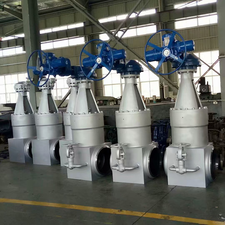
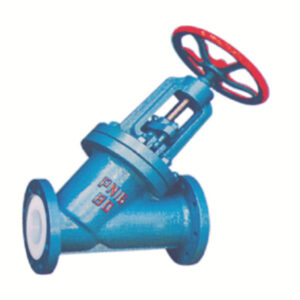
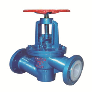
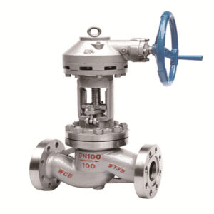
To prevent unqualified valves from being mixed on site, each valve must be pressure tested before leaving the factory.
The valve pressure tester can meet the pressure test items of various valves, including:
- Valve shell test
- Superior sealing performance test
- High pressure leak test
- Low pressure leak test
- Other tests.
Method for evaluating the valve pressure test before it leaves the factory
(1) Install the valve
Place the valve under test on the sealing plate under the bench.
(2) Clamping valve
Method of locking the flanged valve
I. Install the flat sealing plate.
II. Put the sealing ring into the flat sealing plate.
III. Test the valve on the bottom sealing plate and align it.
IV. Press the “Clamp” button and work with the “Pressure adjustment” knob to lock the valve.
(3) Waterway connection of valve pressure testing machine
Connect the water inlet of the appliance to the water source with the supplied water hose, turn on the water
source switch and fill the water tank with water. When the water tank is full, water flows out of the overflow
door and the water source must be closed.
(4) Operation of the oil circuit and circuit of the valve pressure testing machine
I. Turn on the power.
II. After closing the choke, the power light turns on.
III. Unscrew the “Pressure adjustment” knob anticlockwise and press the “Pump Start” switch to start the oil pump. At this time, you can perform other actions.
IV. To reduce the hydraulic shock after each action of the oil cylinder, each time you switch to the front,you need to turn the “pressure adjustment” knob counterclockwise, so that the “pressure meter reading” system “is less than 2 MPa.V. The “sealed oil cylinder” has a hydraulically controlled check valve. After pressing the “release” button it is not possible to immediately reverse the direction, but it is necessary to turn the “pressure adjustment” knob clockwise to ensure that the pressure of the oil circuit system exceeds a certain
value (generally 2 -3MPa), the action will start.
VI. Turn the “pressure adjustment” knob and the action must be gentle, otherwise it will cause a shock and the pressure gauge reading will rise too fast.
(5) Leak test (tightness) of the valve
Valve leak test
I. Lock the valve to be tested and the “holding pressure” value is calculated according to the “pressure comparison table and calculation formula” according to different valve diameters and pressures.
II. Open the pressure relief valve, turn on the low pressure water pump switch, until the water comes out of the pressure relief port, close the opening and closing
parts of the valve under test until the lancet of the pressure gauge starts to move, and then close the low pressure water pump.
III. Press the “pressure on” switch, then turn the “pressure adjustment” knob clockwise to make the test pressure gauge reading reach the value to be tested, turn on the “pressure hold timing” switch, the time relay starts timing and when the set time is reached, “Buzzer” starts to sound.
*According to GB4981 and ISO5208-1982, the test pressure should be 1.1 times the maximum allowable working pressure at 20 ° C. According to ZBJ16006-90, the test pressure should be 1.1 times the pressure nominal at 38 ° C), (the small diameter low pressure valves must cooperate with the “Pressure Speed” knob, the knob must be turned to the minimum counter-clockwise before pressing.
IV. We observe and evaluate whether or not the tested valve is qualified by the pressure drop during the entire duration of the test.
V. At the end of the test, open the “overpressure switch” to reset the test pressure gauge to zero. Then turn the “pressure adjustment” knob counterclockwise to make the system pressure less than 0.5 MPa.
VI. Press the “release” button, turn the “pressure adjustment” knob clockwise to loosen the valve under test, then turn the “pressure adjustment” knob counterclockwise to make the system pressure less than 0.5 MPa.
VII. Remove the valve under test. The inspection of a valve is completed.
Test the strength of the valve shell and the sealing performance of the upper seal
I. Select the corresponding sealing disc according to the diameter and connection form of the valve to be tested.
II. Place the valve under test on the lower sealing plate and align it. Then press the “clamp” button to clamp the valve under test, and the clamping force is calculated according to the comparison table and formula.
III. Unscrew the valve opening and closing parts; open the left pressure relief and inject water into the valve under test until the water flows out from the pressure relief port. Then close the relief valve.
IV. The test steps are the same as those of “valve seal test“
Gas sealing test of valve pressure testing machine
I. Open the rear door of the chassis, and open the water-air switching valve to connect the air circuit. Note: The water-gas switching valve must be closed during the water pressure test
II. Turn off the “pressure relief” switch.
III. Connect the medium gas source (nitrogen) and the power gas source (compressed air) to the gas booster pump respectively.
IV. Turn on the “medium gas switch” first, and then turn on the “power gas switch” after the pressure rises to perform a pressure test. If it is lower than the nitrogen cylinder pressure, only slowly open the “medium gas switch” to perform the pressure test. We judge whether the valve under test is qualified or not by the pressure drop during the test duration. (If the operation panel is equipped with two test pressure gauges, high and low pressure. The use of high and low pressure gauges is beneficial to improve measurement accuracy at low pressure. PAY ATTENTION! When the test pressure is greater than 2/3 of the range, be sure to the low pressure meter switch is closed to prevent the low pressure meter from being damaged.
V. After the test is completed, turn on the pressure relief switch to complete the pressure relief.
VI. Press the “release” button, turn the “pressure adjustment” knob clockwise to loosen the valve under test, and then turn the “pressure adjustment” knob counterclockwise to make the system pressure less than 0.5MPa, and remove the valve.
(6) Requirements for valve test work
I. The operator should be familiar with and master the operation skills of the equipment, otherwise, he will not be allowed to work.
II. Do not dismantle the equipment at will, if abnormal conditions are found, the power supply should be cut off, and the maintenance personnel should be notified for maintenance.
III. The hydraulic valve test bench to be tested should be placed in the center of the platform to prevent the workpiece from being deformed by force and other accidents.
IV. Press the hydraulic valve test bench to the specified pressure according to the technical data.
V. After the hydraulic valve test, it should be released and unloaded in time, and the rotating parts should be restored to the initial state.
VI. When loading, unloading and stacking the valve, handle it with care to prevent the outer surface from being bruised.
VII. The valves after the pressure test must be positioned separately according to the test results and must also be marked. Clean the flange surface and water traces of the flow holes, then apply the anti-rust oil. Now the staff who carried out the pressure test delivered the valves to the warehouse for acceptance by the inspector.)
VIII. Fill in the pressure test record of the hydraulic valve test stand in a timely and truthful manner.


