Construction Industry
Within the plumbing systems of buildings, valves play the role of controlling fluids, and due to the difference in construction structure and material, the valves produced may also be different. To ensure that the piping system can achieve maximum efficiency, lowest cost and longest life, the valve must be selected with care and attention.
The valve in the construction sector mainly performs 4 main functions:
1. Start and stop the flow of the medium
2. Adjust the flow of the medium
3. Prevent ebb or ebb
4. Adjust or release fluid pressure
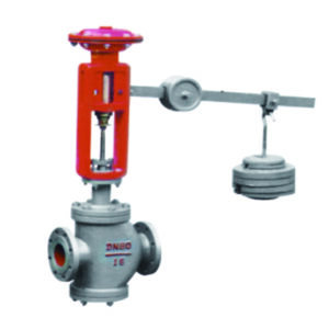
The choice of building piping system is made based on factors such as temperature and type of fluid. For example, a warning valve should be used for the control valve of a fire hydrant in a high-rise building, which is the key to determining whether the fire hydrant system can reasonably be used in a fire. Status can be viewed in the fire control center for easy inspection by managers. Although the cost has increased, the ratio of its investment to the entire fire hydrant system is still very small and can greatly improve the safety of the entire fire hydrant system. The investment is still worth it.
The selection of the
type of valve in the building piping system must be selected based on the characteristics of the building. If the valve used does not meet the design characteristics of the building, many potential hidden dangers will continue to appear. 6 types of valves commonly used in building water supply and drainage projects are introduced below There are many types of valves, but those commonly used in building water supply and drainage projects can be divided into:
Based on the engine power we can further classify them in: manual
- electric
- hydraulics
- pneumaticsOn the basis of the engineering pressure, on the other hand, we recall the valves at:
- high pressure (PN100 ~ PN1000, excluding PN100)
- medium pressure (PN16 ~ PN100, excluding PN16)
- low pressure (≤PN16), super high pressure valve (≥PN1000) According to the temperature there are valves at:
- high temperature (t ﹥ 425 ℃)
- average temperature (120 ℃ ≤t≤425 ℃)
- normal temperature (-29 ℃ < t < 120 ℃)
- low temperature (-100 ℃ ≤ t≤-29 ℃)
- very low temperature valve (t < -100 ℃)
Most of the valves commonly used in water supply and drainage projects are low pressure and normal temperature valves or medium pressure and normal temperature valves, mostly manual.
The last classification is based on the material that makes up the valve:
- cast iron
- cast steel
- copper
- stainless steel
- plastic
- composite material (plastic coating, rubber coating, alloy, enamel, etc.)
Butterfly valve
(DN> 50mm domestic water supply pipe adopts butterfly valve, stainless steel valve core or copper core) The structure
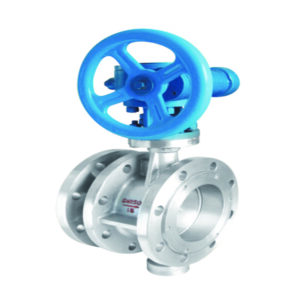
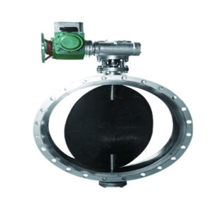
type of the butterfly valve is divided into centerline type and eccentric type according to its disc position, while according to its connection shape, it is divided into flanged connection and wafer connection.
Butterfly valves for water supply lines and butterfly valves for other purposes with a nominal pressure greater than PN10 should not use gray cast iron to make pressurized parts such as valve bodies and butterfly plates. The zinc content of the copper alloy parts in contact with drinking water must be less than 16% and the lead content must not exceed 8%. When the butterfly valve is used in drinking water pipelines, it must comply with the GB / T17219 “Safety of drinking water transmission and distribution equipment and protective materials” evaluation standard.
The butterfly valve seal is divided into:
Single seal
The one-way sealing butterfly valve is that when the front of the butterfly valve is closed, it must face the direction of the fluid flow; the fluid only flows in one direction and there should be an arrow on the valve body indicating the direction of the fluid flow. During installation, pay attention to the direction of fluid flow.
Double seal
The two-way seal butterfly valve is the direction of fluid flow towards which the butterfly plate can face or face out. There is no need to pay attention to the fluid flow direction during installation, and there is no arrow indicating the fluid flow direction on the valve body. The stem force of the two-way seal butterfly valve is greater than tha n that of the one-way seal butterfly valve. In design, for the butterfly valve of the same diameter and pressure, the stem diameter of the two-way seal butterfly valve is larger than that of the one-way seal butterfly valve. The medium and low pressure valves commonly used in water supply and drainage and fire systems are midline butterfly valves.
Butterfly valve examples:
- Handle the actuator to lock the center line type rubber seal carbon steel butterfly valve
- Handle the throttle valve of the drive flange centerline rubber seal
- With rubber midline seal of worm gear
- With rubber seal of worm gear flange centerline
- Steel with electrical terminal centerline rubber seal
Globe valve
(Domestic water supply pipe DN <50 mm adopts a globe valve all made of copper) The
globe valve is a force-sealed valve, so when the valve is closed, pressure must be applied to the valve disc to force the sealing surface not to leak. As fluid enters the valve from under the valve disc, the resistance that the operating force must overcome is the frictional force between the valve stem and the packing and the thrust generated by the fluid pressure. The force to close the valve is greater than the force to open the valve, so the stem diameter should be large, otherwise it will fail.
According to the connection method, it is divided into three types:
After the appearance of the self-sealing valve, the direction of the medium flow of the globe valve is changed from the top of the valve disc into the valve cavity. Under the action of medium pressure, the force to close the valve is small but the force to open the valve is large, and the valve stem diameter can be adjusted accordingly. At the same time, under the action of the medium, this valve form is also narrower. The flow direction of the globe valve must always be from top to bottom. When the globe valve is open, when the valve disc opening height is between 25% and 30% of the nominal diameter, the flow has reached its maximum, indicating that the valve has reached the fully open position. Therefore, the fully open position of the globe valve should be determined by the valve disc stroke.
Globe stop valve examples:
- Copper sealed with direct through copper with manual internal thread
- In copper watertight copper with manual flange connection
Gate valve
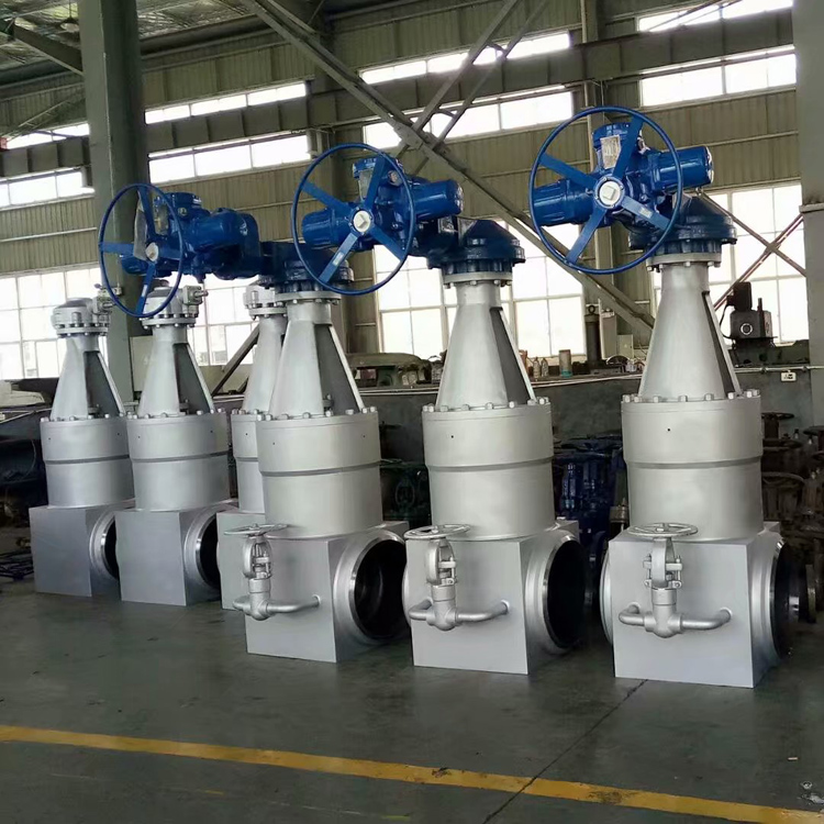
Open stem ductile iron gate valve is used on the inlet pipe and outlet pipe of the fire pump, and the other parts use a two-way butterfly valve. The gate valve is both opening and closing and the direction of movement of the gate is perpendicular to the direction of the fluid. The gate can only be fully open and fully closed and cannot be adjusted or throttled and is sealed by contact between the valve seat and the gate plate. Usually, the sealing surface will be coated with metallic materials to increase wear resistance, such as 1Cr13, STL6 or stainless steel coating.
The gate has a rigid part and an elastic part, which means that the gate can be rigid or elastic. The flow resistance of the gate valve is very low as the fluid channel inside the valve body goes straight and flows in a straight line. Therefore, with respect to the globe valve, the direction of movement of the penstock
is perpendicular to the direction of the fluid flow. The opening and closing stroke of the gate is wide and the lifting and lowering are carried out by the screw. The fluid can flow in any direction on either side and is easy to install. The penstock channel is symmetrical
on both sides. The shape is simple, the length of the structure is short, the production process is good, and the scope of application is wide.
Gate valve examples:
- In ductile cast iron with open stem wedge rubber gasket with flange connection
- In ductile cast iron with dark rod wedge rubber gasket with flange connection
- Ductile iron with dark stem wedge single plate rubber gasket with geographic flange connection
Check valve
The waterproof hammer silencer
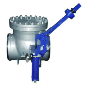
check valves are installed on the outlet pipes of the life and fire pumps, while the ball check valves are installed on the outlet pipes of the submersible sewage pumps, and other parts are ordinary check valves.
Depending on the structure, check valves can be divided into 3 types:
- lift-up (vertical and straight-through)
- hinged (single-lobed, double-lobed and multi-lobed)
- butterfly (double butterfly flap and single butterfly flap)
The connection form of the above check valves can be divided into 4 types:
- threaded
- flange
- welding
- wafer
The materials are: cast iron, brass, stainless steel, carbon steel, forged steel, etc.
Direct lift check valves must be installed on horizontal pipes; vertical lift check valves are usually installed on vertical pipes and the fluid flows from the bottom up; vertical lift check valves can also be installed on horizontal pipes.
The installation position of the
swing check valve is not limited, it is usually installed on the horizontal pipeline, but also can be installed on the vertical pipeline or drain pipeline.
Check valve examples:
- Stainless steel silencer with vertical metal seal with flange lift
- Mute check valve in ductile iron with vertical rubber seal with lan lifting
- For noise reduction made of ductile iron with vertical rubber seal with lan lift
- Of the stainless steel silencer with blue lifting vertical metal seal
- I cast steel (stainless steel) sealed in Lansheng oscillating one-piece copper
- In ductile cast iron with oscillating double flap rubber gasket
- Spheroidal cast iron ball with flange lifter rubber gasket
- Slow closing
Pressure reducing valve
The main water supply pipe adopts adjustable or proportional pressure reducer, and the water supply pipe adopts AD type pressure reducer.
There are many types of pressure reducers including:
- spring diaphragm
- proportional
- adjustable pilot
- type AD
1) When the pressure behind the valve can fluctuate, a proportional pressure reducer must be used. The valve uses the pressure difference generated by the different areas of the piston cross section within the valve body to change the pressure after the valve to achieve the decompression purpose. It can be installed horizontally or vertically.
The pressure reduction ratio of the proportional pressure reducer is:
2: 1
3: 1
4: 1
3: 2
5: 2
Etc.
When selected, the decompression ratio must not be greater than 3: 1.
When it is greater than 3: 1, the cavitation area should be avoided.
2) When it is necessary for the pressure behind the valve to be stable, it is necessary to use an adjustable pressure reducer. When DN≤50mm, use direct type pressure reducer, when 50mm≤DN≤100mm, use direct or pilot type pressure reducer, when DN> 100mm, use pilot type. The pressure difference between the front and back of the adjustable pressure reducer should not be greater than 0.40 MPa and the place requiring a quiet environment should not be greater than 0.30 MPa. According to the principle of hydraulic differential control or hydraulic pilot control (the main valve is controlled by the pressure reducing pilot valve) and the set value of the output pressure prevails, the degree of opening and the flow rate of the valve disc are automatically adjusted on realizing the decompression and stability of the outlet pressure. and the degree of correlation with the inlet pressure is small, and the outlet pressure of the pressure reducer can be effectively adjusted by the spring adjusting device.
3) AD type pressure reducer is a direct acting film spring pressure reducer, designed and manufactured on the basis of absorbing the advantages of similar foreign products. It is mainly composed of diaphragms, flaps, adjusting springs and other parts. The diaphragm is used to detect the downstream pressure change to operate the valve disc, modify and control the valve opening to achieve the decompression and voltage regulation function. AD type pressure reducer uses a bracket-shaped connecting hook to connect the diaphragm and valve disc together, which has a high adaptability to water quality, does not stick and does not need a filter. No maintenance is required and no bypass hose is required. The AD type pressure reducer has a pressure reducer for both the main pipe and the branch pipe.
Exhaust valve
The automatic drain valve is divided into:
- great
- micro
- composite according to the size of the waste volume
The structure of the drain valve is divided into two types:
- floating ball plus lever mechanism
- floating ball with direct action
The composite drain valve integrates mass drain and micro drain functions and is widely used in municipal piping networks, building water supply and fire protection systems, especially in dry fire protection systems. The DN15 drain valve we usually design and choose is generally used for water supply, hot water, fire hydrant system, automatic wet sprinkler system, water spray system, deluge system, etc.
CARX-0025 type drain valve is a composite drain valve, also commonly known as quick drain valve, generally used in dry irrigation systems, preaction irrigation systems, dry irrigation systems. The principle of operation of the automatic drain valve is based on the fact that, when there is air in the system, the gas accumulates on the top of the drain valve and the accumulation of bubbles in the body causes the float ball to fall with the level water, then the exhaust piston is open. After the gas is exhausted, the water level rises and the floating ball also rises, closing the exhaust piston. If you tighten the cover on the side of the valve body, the drain valve stops discharging. Normally, the hood should be open.
Exhaust valve examples:
- Drain micro-valve
- Compound exhaust valve


