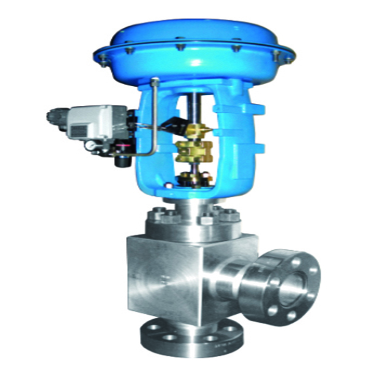
ZMAS High Pressure Angle Control Valve
Detailed introduction:
The supplier of “ZMAS High Pressure Angle Control Valve”, the “pneumatic control valve” supplied by our company is of high quality, reasonable price, and perfect after-sales service. “ZMAS High Pressure Angle Control Valve” is suitable for light and heavy industry and building pipelines. On the way forward, let Xinhui Valve solve your problems! [Regulating valve] can be used in: chemical, petrochemical, petroleum, papermaking, mining, electric power, liquefied gas, food, pharmaceutical, water supply and drainage, municipal, mechanical equipment, electronic industry, urban construction, and other fields.
| product name | ZMAS High Pressure Angle Control Valve |
| Product number | NEQJT |
| Nominal diameter | DN15-150 |
| pressure range | 1. 0-6. 4MPa |
| valve body material | Cast iron丨ductile iron丨cast steel丨stainless steel |
[Control valve] valve body type selection: There are many types of valve bodies for control valves, and the commonly used valve body types include
① straight-through single seat
② straight-through double seat
③ angle
④ diaphragm
⑤ small flow
⑥ three-way
⑦ eccentric rotation
⑧ butterfly
⑨ sleeve Cylinder type
⑩ spherical and so on.
[Regulating valve] The following considerations can be made in the specific selection:
(1) The shape and structure of the valve core: It is mainly considered according to the selected flow characteristics and unbalanced force.
(2) Wear resistance: When the fluid medium is a suspension containing a high concentration of abrasive particles, the internal material of the valve should be hard.
(3) Corrosion resistance: Since the medium is corrosive, try to choose a valve with a simple structure.
(4) The temperature and pressure of the medium: when the temperature and pressure of the medium are high and the change is large, the valve core and the valve seat material should be selected with small changes in temperature and pressure. When the temperature is 250°C, a radiator should be added. .
(5) Prevent flash evaporation and cavitation: Flash evaporation and cavitation only occur in liquid media. In the actual production process, flash evaporation and cavitation will form vibration and noise, shorten the use of the valve, so the valve should be prevented from flashing and cavitation when selecting the valve. Overview of ZMAS High Pressure Angle Control Valve:
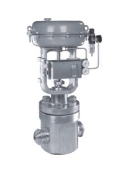
ZMAS High Pressure Angle Control Valve is composed of pneumatic multi-spring diaphragm actuator and low flow resistance single seat valve. The new actuator is low in height, light in weight and easy to install. The new valve body has a compact structure, a smooth flow channel and a large flow coefficient. This product operates stably, has good action characteristics, small valve seat leakage, accurate flow characteristics, and a wide adjustable range. It has the advantage of achieving high quality control in the application. Products include standard type, adjustable cut-off type, bellows seal type, jacket insulation type, etc.
Variety. Applicable to various grades of liquid temperature ranging from -200^ to +560C. (Accessories available: positioner, air filter pressure reducer, position retaining valve, travel switch, valve position transmitter, solenoid valve, handwheel mechanism, etc.)
[1] ZMAS High Pressure Angle Control Valve Performance Index:
| Project | Index value | project | Index value | ||||
| Basic Error % | Without positioner | ±5.0 |
Start point end point deviation % |
air shut |
Without positioner |
start point |
±5. 0 |
| With positioner | ±1.0 |
end point |
±2. 5 | ||||
|
Return difference % |
Without positioner | <3.0 |
With positioner |
start point |
±1.0 | ||
|
end point |
±1.0 | ||||||
|
With positioner |
<1.0 |
air open |
Without positioner |
start point |
±2. 5 | ||
|
end point |
±5. 0 | ||||||
|
Dead zone |
Without positioner | <3.0 |
With positioner |
start point |
±1.0 | ||
|
end point |
±1.0 | ||||||
|
With positioner |
<0.4 |
Allowable leakage L/h |
1X10⁻⁴X Valve Rated Capacity | ||||
|
Rated stroke deviation% |
±2.5 | ||||||
Note: This product implements the national standard GB/T4213-92.
[2] Allowable differential pressure MPa:
| Switching method | Actuator Model | spring range
KPa |
Air source pressure
KPa |
Attachment required | Nominal diameter (valve seat diameter) mm | |||||||||||||||
| 25 | 25 | 40 | 50 | 65 | 80 | 100 | 150 | 200 | 250 | 300 | ||||||||||
| (10) | (12) | (15) | (20) | (32) | (40) | (125) | (150) | |||||||||||||
| air shut | ZHA
-22 |
20〜
100 20〜 100 40〜 200 |
140
250 140 |
P
P P or R |
6.4
6.4 6.4 |
5.94
6.4 6.4 |
3.34
6.4 6.4 |
3.34
6.4 6.4 |
2.14
6.4 6.4 |
|||||||||||
| ZHA
-23 |
20〜
100 20〜 100 40〜 200 |
140
250 400 |
P
P P or R |
1. 31
6. 09 6.4 |
0. 84
3.9 5.26 |
0.5
3 2.5 3.3 9 |
||||||||||||||
| ZHA | 20〜 | 140 | P | 0.5 | 0. | 0.21 | ||||||||||||||
| -34 | 100 | 250 | P | 1 | 33 | 1.0 | ||||||||||||||
| 20〜 | 400 | P | 2.3 | 1. | 1.35 | |||||||||||||||
| 100 | or | 6 | 56 | |||||||||||||||||
| 40〜 | R | 3.2 | 2. | |||||||||||||||||
| 200 | 1 | 12 | ||||||||||||||||||
| ZHA | 20〜 | 140 | P | 0.22 | 0.15 | 0.08 | ||||||||||||||
| -45 | 100 | 250 | P | 1.02 | 0. 71 | 0.40 | ||||||||||||||
| 20〜 | 400 | P | 1.39 | 0. 97 | 0.54 | |||||||||||||||
| 100 | or | |||||||||||||||||||
| 40〜 | R | |||||||||||||||||||
| 200 | ||||||||||||||||||||
| ZHA | 20〜 | 140 | P | 0.06 | 0.04 | |||||||||||||||
| -56 | 100 | 250 | P | 0.37 | 0.25 | |||||||||||||||
| 20〜 | 400 | P | 0.51 | 0.36 | ||||||||||||||||
| 100 | or | |||||||||||||||||||
| 40〜 | R | |||||||||||||||||||
| 200 |
| air open | ZHB | 20〜 | 140 | P | 4.46 | 3. 09 | 1.98 | 1.11 | 0. 71 | |||||||||||
| -22 | 100 | 250 | P | 6.4 | 6.4 | 5.94 | 3.34 | 2.14 | ||||||||||||
| 40〜 | 400 | or | 6.4 | 6.4 | 6.4 | 6.4 | 4.99 | |||||||||||||
| 200 | R | |||||||||||||||||||
| 80〜 | P | |||||||||||||||||||
| 240 | ||||||||||||||||||||
| ZHB | 20〜 | 140 | P | 0.44 | 0.28 | 0.1 | ||||||||||||||
| -23 | 100 | 250 | P | 1.37 | 0.84 | 8 | ||||||||||||||
| 40〜 | 400 | or | 3.05 | 1.95 | 0.5 | |||||||||||||||
| 200 | R | 3 | ||||||||||||||||||
| 80〜 | P | 1.2 | ||||||||||||||||||
| 240 | 5 | |||||||||||||||||||
| ZHB | 20〜 | 140 | P | 0.1 | 0. | 0.07 | ||||||||||||||
| -34 | 100 | 250 | P | 7 | 11 | 0.21 | ||||||||||||||
| 40〜 | 400 | or | 0.5 | 0. | 0.5 | |||||||||||||||
| 200 | R | 1 | 33 | |||||||||||||||||
| 80〜 | P | 1.1 | 0. | |||||||||||||||||
| 240 | 8 | 78 | ||||||||||||||||||
| ZHB | 20〜 | 140 | P | 0.07 | 0.05 | 0.02 | ||||||||||||||
| -45 | 100 | 250 | P | 0.22 | 0.15 | 8 | ||||||||||||||
| 40〜 | 400 | or | 0.51 | 0.35 | 0.08 | |||||||||||||||
| 200 | R | 0.20 | ||||||||||||||||||
| 80〜 | P | |||||||||||||||||||
| 240 | ||||||||||||||||||||
| ZHA | 20〜 | 140 | P | 0.03 | 0.02 | |||||||||||||||
| -56 | 100 | 250 | P | 0.09 | 0.06 | |||||||||||||||
| 20〜 | 400 | P | 0.20 | 0.14 | ||||||||||||||||
| 100 | or | |||||||||||||||||||
| 40〜 | R | |||||||||||||||||||
| 200 |
Note: (1) P-Valve Positioner; R-Pressure Relay; (2) Allowable differential pressure for valve closing P2=. (3) If the allowable pressure difference is unclear or the maximum working pressure difference is beyond the list, please contact us.
【three】main parts material:
| Part Name | Material | temperature range |
| valve body top valve cover | HT200 | -20〜200°C |
| ZG230-450 | -40〜450°C | |
| ZG1Cr18Ni9Ti | -250—550C | |
| ZG0Cr18Ni12Mo2Ti | -250—550C | |
| valve core, valve seat | 1Cr18Ni9 | -250—550C |
| 0Cr18Ni12Mo2Ti | -250—550C | |
| packing | polytetrafluoroethylene | -40〜200C |
| Diaphragm | Nitrile rubber clip reinforced polyester fabric | |
| compressed spring | 60Si2Mn | |
| Membrane cover | A3 |
[4] The main technical parameters of the adjustment mechanism:
| Nominal diameter mm | 20 | 25 | 40 | 50 | 65 | 80 | 100 | 150 | 200 | 250 | 300 | 350 | 400 | |||||||
| Diameter of valve seat mm | 10 | 12 | 15 | 20 | 25 | 32 | 40 | 50 | 65 | 80 | 100 | 125 | 150 | 200 | 250 | 300 | ||||
| Nominal flow
Coefficient Kv |
straight line equal percentage | 1. 8 | 2. 8 | 4.4 | 6.9 | 11 | 17. 6 | 27. 5 | 44 | 69 | 110 | 176 | 275 | 440 | 690 | 1000 | 1600 | |||
| 1. 6 | 2. 5 | 4 | 6.3 | 10 | 16 | 25 | 40 | 63 | 100 | 160 | 250 | 400 | 630 | 900 | 1440 | |||||
| Nominal pressure MPa | 0. 6 1. 6 4. 0 6. 4 | |||||||||||||||||||
| stroke mm | 10 | 16 | 25 | 40 | 60 | 100 | ||||||||||||||
| Traffic characteristics | Straight line, equal percentage, quick opening | |||||||||||||||||||
| Media temperature C | -40-230C (normal temperature type), heat sink type 230-450C (medium temperature type), customized -100~600C | |||||||||||||||||||
| Flange Standard | Comply with JB78-59, JB79-59 standards, can be ordered according to JB/79.1-94, JB/79.2-94, ANSI, JIS, DIN and other standards | |||||||||||||||||||
| valve body material | PN
(MPa) |
0. 6, 1.6 | WCB(ZG230-450) CF3CF8 CF8M | |||||||||||||||||
| 4. 0, 6.4 | WCB(ZG230-450), ZG1Cr18Ni9Ti、 ZG0Cr18Ni12Mo2Ti CF8 CF8M | |||||||||||||||||||
| valve body type | Straight Single Seat Cast Ball Valve | |||||||||||||||||||
| Valve core material | 1Cr18Ni9、 0Cr18Ni12Mo2Ti CF8 CF8M | |||||||||||||||||||
| Upper valve cover form | Common type (normal temperature type), hot plate type (medium temperature type), low temperature type | |||||||||||||||||||
| Adjustable ratio R | 50:1 | |||||||||||||||||||
| Gas source connector | M16X1. 5 | |||||||||||||||||||
Note: ANSI and JIS flanged products can be provided for users, and the structural length can also be determined according to user needs.
【V】Main technical parameters of the actuator:
| model | ZHA-22
ZHB-22 |
ZHA-23
ZHB-23 |
ZHB-34
ZHB-34 |
ZHA-45
ZHB-45 |
ZHA-56
ZHB-56 |
| Effective area cm2 | 350 | 350 | 560 | 900 | 1600 |
| stroke mm | 16 | 25 | 40 | 60 | 100 |
| Spring range KPa | 20—100(standard):40〜200;
80〜240; 20—60; 60〜100 |
||||
【Six】ZMAS High Pressure Angle Control Valve Dimensions mm:
| DN | L | H | H1 | weight (kg) | 0A | |||||||
| PN16 | PN40 | PN64 | general | high temperature | PN6 | PN16 | PN40 | PN64 | PN6
PN16 |
PN40
PN64 |
||
| 20 | 181 | 194 | 206 | 398 | 548 | 45 | 52 | 65 | 19 | 23 | 285 | |
| 25 | 185 | 197 | 210 | 410 | 560 | 50 | 57 | 70 | 20 | 24 | ||
| 40 | 222 | 235 | 251 | 455 | 620 | 65 | 75 | 85 | 26 | 35 | ||
| 50 | 254 | 267 | 286 | 457 | 627 | 70 | 82 | 90 | 30 | 40 | ||
| 65 | 276 | 292 | 311 | 610 | 790 | 80 | 92 | 100 | 47 | 66 | 360 | |
| 80 | 298 | 317 | 337 | 622 | 807 | 95 | 100 | 107 | 55 | 78 | ||
| 100 | 352 | 368 | 394 | 640 | 850 | 105 | 110 | 117 | 125 | 65 | 99 | |
| 150 | 451 | 473 | 508 | 870 | 1130 | 132 | 142 | 150 | 172 | 130 | 160 | 470 |
| 200 | 600 | 650 | 890 | 1150 | 160 | 170 | 187 | 207 | 175 | 250 | ||
| 250 | 730 | 775 | 1203 | 1523 | 187 | 202 | 225 | 235 | 350 | 470 | 580 | |
| 300 | 850 | 900 | 1234 | 1554 | 220 | 230 | 257 | 265 | 500 | 660 | ||
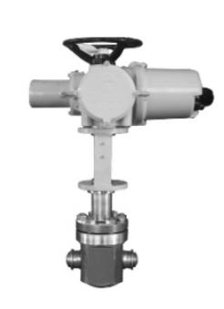
[Regulating valve] It consists of two parts: an electric actuator or pneumatic actuator and regulating valve. The regulating valve is divided into an electric regulating valve, a pneumatic regulating valve, and a hydraulic regulating valve (self-operated regulating valve). The regulating valve is used to regulate the flow, pressure, and liquid level of the medium. According to the signal of the adjustment part, the opening of the valve is automatically controlled, so as to achieve the adjustment of medium flow, pressure, and liquid level. [Control valve] is usually divided into two types: straight-through single-seat control valve and straight-through double-seat control valve. The latter has the characteristics of large flow capacity, small unbalance, and stable operation, so it is usually suitable for large flow, high-pressure drop, and Occasions with little leakage. The flow capacity Cv is one of the main parameters for selecting the control valve. The flow capacity of the control valve is defined as when the control valve is fully opened, the pressure difference between the two ends of the valve is 0.1MPa, and the fluid density is Lg/cm3, the flow rate per hour is The flow rate of the diameter control valve, called the flow capacity, also called the flow coefficient, is expressed in Cv, the unit is t/h, and the Cv value of the liquid is calculated as follows.


Reviews
There are no reviews yet.