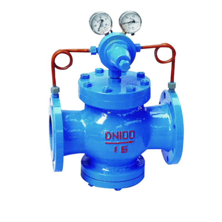
Pilot piston type gas pressure reducing valve
The working principle of the steam pressure reducing valve is to adjust the flow of the medium by controlling the opening of the opening and closing parts in the valve body, and reduce the pressure of the medium. Within a certain range, when the inlet pressure is constantly changing, keep the outlet pressure within the set range to protect subsequent living and production appliances. This type of valve should generally be installed horizontally in the pipeline. The steam pressure reducing valve is an essential accessory of the pneumatic control valve. Its main function is to reduce the pressure of the air source and stabilize it to a certain value, so that the control valve can obtain stable air source power for regulation and control. The work of the steam pressure reducing valve is controlled by the pressure behind the valve. When the pressure sensor detects that the valve pressure indication rises, the valve opening of the pressure reducing valve decreases; when the pressure decreases after detecting the pressure reducing valve, the valve opening of the pressure reducing valve increases to meet the control requirements. Steam Pressure Reducing Valve—The valve must have a pressure reduction ratio somewhat higher than the system value; it should be able to respond to direct or reverse acting control signals even at maximum or minimum flow. These valves should be selected for the useful control range, which is 20% to 80% of maximum flow. Normally isometric or has isometric properties.
Working principle of piston pressure reducing valve: when the pressure reducing valve leaves the factory, the adjustment spring is in the uncompressed state, at this time the main valve disc and the auxiliary valve disc are in the closed state, when in use, turn the adjustment screw clockwise to compress the adjustment spring to make the diaphragm The sheet moves down to open the auxiliary valve disc, and the medium enters above the piston from hole a through the auxiliary valve seat to hole b. It enters under the diaphragm through hole c, and when the pressure behind the valve exceeds the set pressure, the diaphragm is pushed up to compress the regulating spring. The auxiliary valve disc moves to the closing direction accordingly, so that the medium flowing into the top of the piston decreases, and the pressure also drops accordingly. The clearance between the main valve and the main valve seat increases, and the medium flow decreases with the pressure after the valve to a new balance. The increase makes the pressure behind the valve increase to reach a new balance.
The gas pressure reducing valve belongs to the pilot piston pressure reducing valve, which consists of two parts: the main valve and the pilot valve. The gas pressure reducing valve is mainly composed of valve seat, main valve disc, piston, spring and other parts. The gas pressure reducing valve is mainly composed of valve seat, valve disc, diaphragm, spring, regulating spring and other parts. Set the outlet pressure by adjusting the spring pressure, use the diaphragm to sense the outlet pressure change, and drive the piston to adjust the flow area of the throttling part of the main valve through the opening and closing of the pilot valve, so as to realize the function of reducing and stabilizing the pressure. The gas pressure reducing valve mainly For gas pipelines, such as air, nitrogen, oxygen, hydrogen, liquefied petroleum gas, natural gas and other gases.
Technical parameters and performance indicators
Material
| Name | Material |
| Valve body,deck,bottom cap | WCB/FCB* |
| Valve seat, disc | 2Cr13/304* |
| Cylinder sleeve | 2Cr13/25(hard chrome plated)/304* |
| Stopcock | 2Cr13/copper alloy/copper alloy* |
| Stopcock ring | Alloy cast iron/para polystyrene* |
| Valve seat,valve rod | 2Cr13/304* |
| Mebrane | 1Cr18Ni9Ti |
| Main valve pilot valve spring | 50CrVA |
| Regulating spring | 60Si2Mn |
| Gasket (X/F model) | Rubber/Teflon |
| Pilot valve body pilot valve deck | 25/304* |
Flow coefficient (Cv)
| DN | 15 | 20 | 25 | 32 | 40 | 50 | 65 | 80 | 100 | 125 | 150 | 200 | 250 | 300 | 350 | 400 | 500 |
| Cv | 1 | 2.5 | 4 | 6.5 | 9 | 16 | 25 | 36 | 64 | 100 | 140 | 250 | 400 | 570 | 780 | 1020 | 1500 |
External dimensions (PN1.6-4.0) unit: mm
| Nominal diameter DN | External dimensions | |||
| L | H | Hl | ||
| 1.6/2.5MPa | 4.0MPa | |||
| 15 | 160 | 180 | 290 | 90 |
| 20 | 160 | 180 | 300 | 98 |
| 25 | 180 | 200 | 300 | 110 |
| 32 | 200 | 220 | 300 | 110 |
| 40 | 220 | 240 | 320 | 125 |
| 50 | 250 | 270 | 320 | 125 |
| 65 | 280 | 300 | 325 | 130 |
| 80 | 310 | 330 | 365 | 160 |
| 100 | 350 | 380 | 365 | 170 |
| 125 | 400 | 450 | 475 | 200 |
| 150 | 450 | 500 | 475 | 210 |
| 200 | 500 | 550 | 515 | 240 |
| 250 | 650 | 560 | 290 | |
| 300 | 800 | 705 | 335 | |
| 350 | 850 | 745 | 375 | |
| 400 | 900 | 780 | 405 | |
| 450 | 900 | 730 | 455 | |
| 500 | 950 | 835 | 465 | |


Reviews
There are no reviews yet.